
Fuel cell galvanic pile hydrogen circulation device and method

A fuel cell stack and circulation device technology, which is applied in the direction of fuel cells, fuel cell additives, fuel cell control, etc., can solve problems such as uneven distribution, and achieve the effect of accelerating the cold start speed

Inactive Publication Date: 2018-09-14
NANTONG BAIYING ENERGY
View PDF0 Cites 9 Cited by
  • Summary
  • Abstract
  • Description
  • Claims
  • Application Information

AI Technical Summary

Problems solved by technology

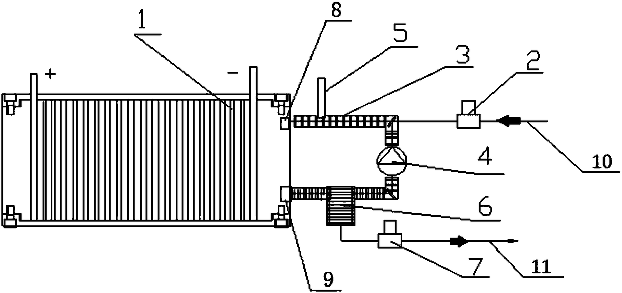
[0008] In order to solve the above-mentioned technical problems of hydrogen circulation, water blocking and uneven distribution of stack water, the present invention provides a hydrogen circulation device for fuel cell stacks, including stacks, hydrogen intake valves, hydrogen circulation pipelines, hydrogen circulation pumps, A temperature sensor, a humidifying water collector and a drain valve; the stack is provided with an anode flow channel inlet and an anode flow channel outlet, and the input end of the humidifying water collector and the anode flow channel outlet are circulated through hydrogen The pipeline is connected, the output end of the humidified water collector is connected with the input end of the hydrogen circulation pump through the hydrogen circulation pipeline, and the output end of the hydrogen circulation pump is connected with the anode flow channel inlet through the hydrogen circulation pipe The temperature sensor is located on the hydrogen circulation pipeline between the output end of the hydrogen circulation pump and the inlet of the anode flow channel, the drain valve communicates with the humidified water collector through a drain pipeline, and the The hydrogen gas intake valve is connected on the hydrogen circulation pipeline between the temperature sensor and the output end of the hydrogen circulation pump through the intake pipeline

Method used


Image

  • Fuel cell galvanic pile hydrogen circulation device and method

Examples


Embodiment Construction

[0019] The following will clearly and completely describe the technical solutions in the embodiments of the present invention with reference to the accompanying drawings in the embodiments of the present invention. Obviously, the described embodiments are only some, not all, embodiments of the present invention. Based on the embodiments of the present invention, all other embodiments obtained by persons of ordinary skill in the art without creative efforts fall within the protection scope of the present invention.

[0020] In the specific embodiment of the present invention, such as figure 1 As shown, a fuel cell stack hydrogen circulation device is specifically disclosed, including a stack 1, a hydrogen intake valve 2, a hydrogen circulation pipeline 3, a hydrogen circulation pump 4, a temperature sensor 5, a humidifying water collector 6 and Drain valve 7; the stack 1 is provided with an anode flow channel inlet 8 and an anode flow channel outlet 9, and the input end of the ...


PUM


Abstract

The invention relates to the technical field of fuel cells, in particular to a fuel cell galvanic pile hydrogen circulation device and a method. An anode flow channel inlet and an anode flow channel outlet are formed in a galvanic pile, an input end of a humidifying water collecting device and the anode flow channel outlet are communicated through a hydrogen circulation pipeline, an output end ofthe humidifying water collecting device is communicated with an input end of a hydrogen circulation pump through the hydrogen circulation pipeline, and an output end of the hydrogen circulation pump and the anode flow channel inlet are communicated through the hydrogen circulation pipeline. The device can adjust the humidity according to the working condition of the galvanic pile, do not let waterblock the flow channels when the power changes, and do not let the inlets of the galvanic pile dry at the high power to damage electrodes and cause the power to drop, and a hydrogen circulation system can heat intake air to speed up the cold start speed during starting at a low temperature, and the problems that uneven distribution of fuel cell water causes the galvanic pile to be partly dried out and even causes the galvanic pile to fail are solved.

Description

technical field [0001] The invention relates to the field of fuel cells, specifically a fuel cell stack hydrogen circulation device and method. Background technique [0002] Proton exchange membrane hydrogen fuel cell (PEMFC) is a kind of fuel cell. When the hydrogen fuel cell forms a loop with an external circuit, the hydrogen on the anode side is converted into hydrogen protons under the action of a catalyst (pt), and combines with water to form hydrated protons. , the oxygen on the cathode side (oxygen in the air) forms oxygen ions under the action of the catalyst (pt), and under the action of the potential difference between the cathode and the anode, the hydronium protons migrate from the anode to the cathode in a directional manner, and combine with the oxygen ions formed at the cathode to form water. At the same time, part of the water enters the anode channel under the action of osmotic pressure, and the external circuit forms an electric current. Thus, the chemical...

Claims


Application Information

Patent Timeline
Patent Type & Authority Applications(China)
IPC IPC(8): H01M8/04089H01M8/04119H01M8/04298
CPCH01M8/04089H01M8/04119H01M8/04298Y02E60/50
Inventor 周江东陈融张宝春
Owner NANTONG BAIYING ENERGY
Learn More