Isolating transformer

A technology of isolation transformers and transformers, which is applied in the field of transformers, can solve the problem of large common-mode interference of isolation transformers, and achieve the effect of reducing the impact

Pending Publication Date: 2018-09-14
BEIJING HUAFENG TEST & CONTROL TECH CO LTD
View PDF5 Cites 4 Cited by
  • Summary
  • Abstract
  • Description
  • Claims
  • Application Information

AI Technical Summary

Problems solved by technology

[0004] In view of this, the main purpose of the present invention is to provide an isolation transformer, which can not only solve the problem of large common-mode interference of the isolation transformer, reduce the electrical coupling generated by parasitic capacitance between the windings, but also reduce the induction at both ends of the shielding layer. The influence of voltage on other windings, eliminate the common mode interference generated by the shielding layer itself, and meet the needs of high-speed and high-precision electrical isolation test and measurement systems

Method used


Image

  • Isolating transformer
  • Isolating transformer
  • Isolating transformer

Examples


Embodiment 1

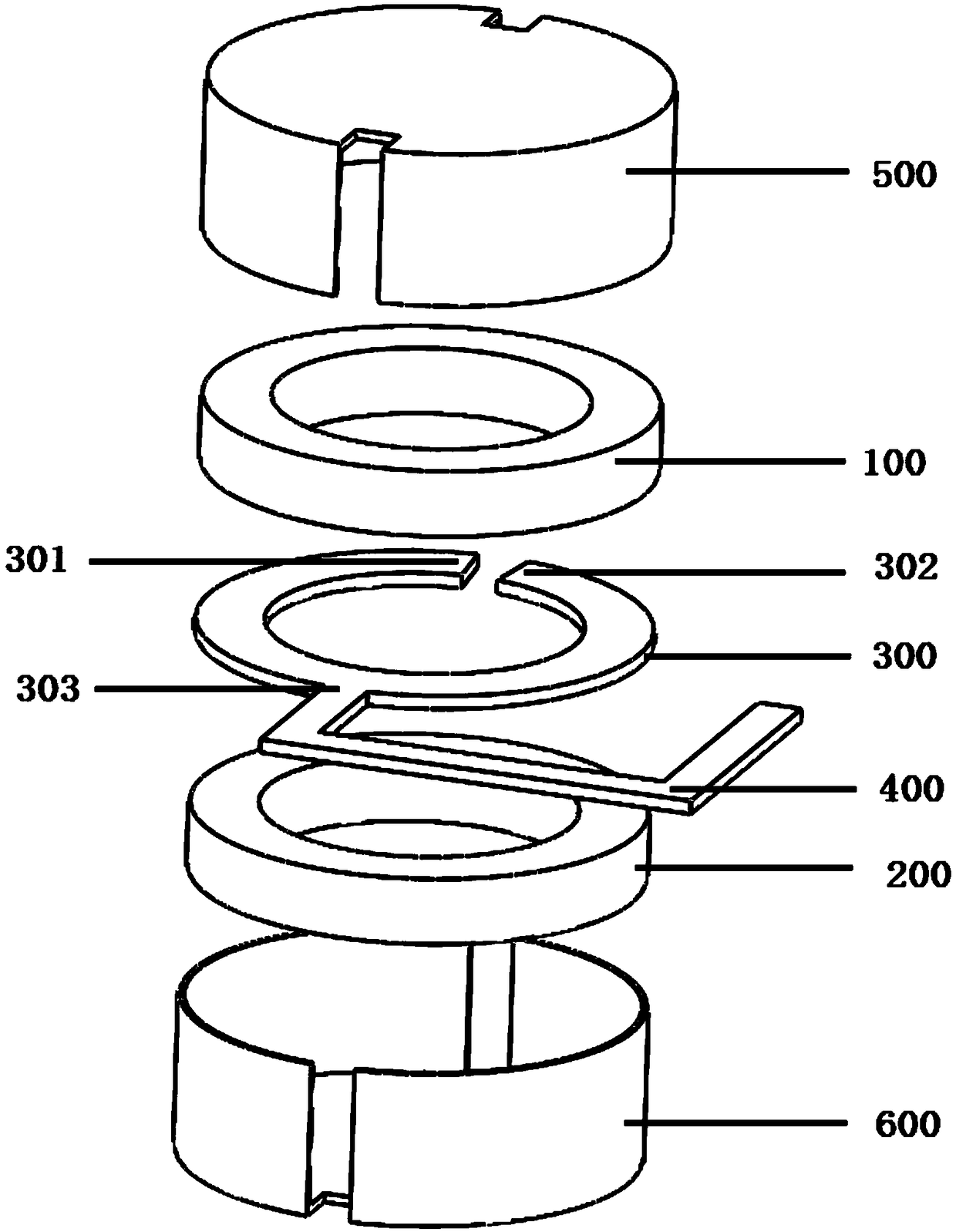
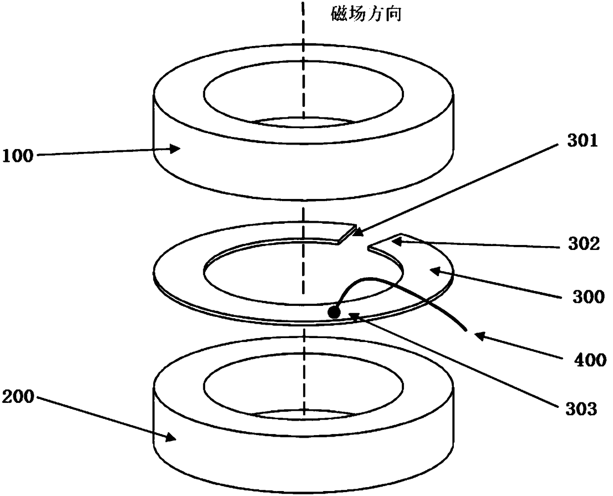
[0032] Such as figure 1 As shown, a preferred embodiment of the present invention provides an isolation transformer with windings arranged up and down, including: magnetic core, magnetic core cover 500, magnetic core base 600, primary winding 100, secondary winding 200, shielding layer 300, the shielding layer potential lead 400, the secondary winding 200 is located at the magnetic core base 600, on which the shielding layer 300, the primary winding 100 and the magnetic core cover 500 are arranged in sequence, the connection between the shielding layer 300 and the shielding layer potential lead 400 The point 303 is located between the two ends 301 and 302 of the shielding layer;

[0033]During specific installation, the turns ratio of the primary winding 100 and the secondary winding 200 is 2:1, a shielding layer 300 is provided between the primary winding 100 and the secondary winding 200, the shielding potential is grounded, and the magnetic core cover 500 and the magnetic c...

Embodiment 2

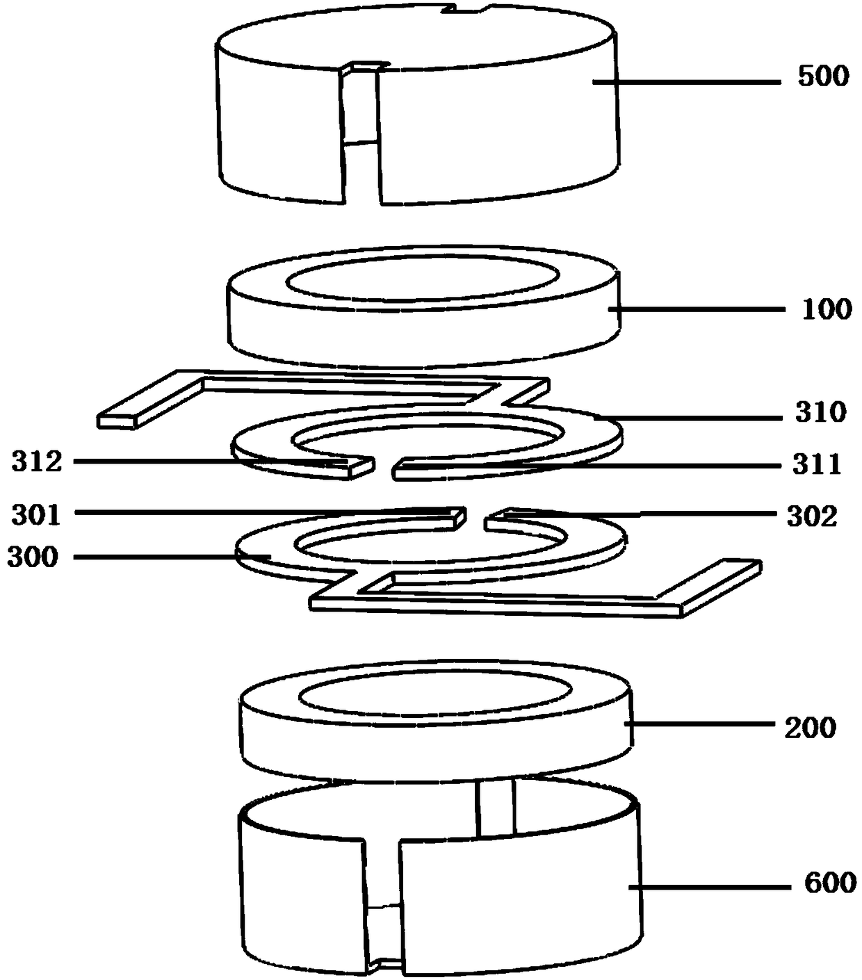
[0040] Such as Figure 5 As shown, another embodiment of the present invention provides a lead position when the winding is arranged inside and outside, including the primary winding 100, the secondary winding 200, the shielding layer 300, and the shielding layer potential lead 400. The secondary winding 200 is located at The outermost side of the transformer is the shielding layer 300 and the primary winding 100 from outside to inside. The connection point 303 between the shielding layer 300 and the shielding layer potential lead 400 is located between the two ends 301 and 302 of the shielding layer. The shielding potential lead 400 Connect the other end to ground.

[0041] Specifically, the working principle of the isolation transformer with windings arranged inside and outside involved in the second embodiment is the same as that of the isolation transformer with windings arranged up and down involved in the first embodiment above. When the shielding layer 300 is connected ...


PUM


Abstract

The invention provides an isolating transformer, which comprises a magnetic core, at least two sets of transformer windings, at least one shielding layer, and a shielding layer potential lead, the shielding layer is located between the two sets of transformer windings, and the joint between the shielding layer and the shielding layer potential lead is located between both ends of the shielding layer. The invention not only can solve the problem of great common-mode interference existing in the isolating transformer, reducing the galvanic coupling generated by parasitic capacitance between thewindings, but also can reduce the influence of induced voltage at both ends of the shielding layer on the other windings, eliminating common-mode interference generated by the shielding layer, and thereby the requirement of high-speed, high-precision electric isolation testing and measurement systems is met.

Description

technical field [0001] The invention relates to the technical field of transformers, in particular to an isolation transformer. Background technique [0002] A high-speed and high-precision electrical isolation test and measurement system requires not only DC low-frequency electrical isolation, but also good high-frequency electrical isolation. High-speed and high-precision electrical isolation test and measurement systems are very sensitive to common-mode interference, and often require common-mode interference to be below tens of millivolts to not affect high-speed precision testing, which requires suppression measures for common-mode interference. As we all know, adding a bypass capacitor between the two isolation grounds of the isolation system will reduce common-mode interference, but the added capacitor will sacrifice high-frequency electrical isolation characteristics, which is not suitable for high-speed and high-precision electrical isolation test and measurement sy...

Claims


Application Information

Patent Timeline
Patent Type & Authority Applications(China)
IPC IPC(8): H01F27/36
CPCH01F27/36
Inventor 孙衍翀
Owner BEIJING HUAFENG TEST & CONTROL TECH CO LTD
Why Eureka
Try Eureka