
Method of calculating centrifugal impeller pre-swirl entry enthalpy rise coefficient based on maximum flow coefficient

A centrifugal impeller, maximum flow technology, which is applied in the components, calculation, and electrical digital data processing of the pumping device for elastic fluid, which can solve the problem of large deviation, ignoring the influence of enthalpy coefficient, and ignoring any pre-precession. Gas and other problems, to achieve the effect of compact structure, accurate and fast calculation, and large flow

Active Publication Date: 2018-09-14
TIANJIN UNIV
View PDF4 Cites 4 Cited by
  • Summary
  • Abstract
  • Description
  • Claims
  • Application Information

AI Technical Summary

Problems solved by technology

At present, in most centrifugal impeller thermodynamic calculations and designs, the enthalpy coefficient is specified as a constant, or only the geometric influence of the impeller outlet (slip factor) is considered, which leads to a large deviation between the calculated enthalpy coefficient and the actual value
Moreover, the existing research only focuses on the axial intake condition, without considering any pre-swirl intake, and does not consider the influence of geometric constraints on the enthalpy coefficient

Method used


Image

  • Method of calculating centrifugal impeller pre-swirl entry enthalpy rise coefficient based on maximum flow coefficient
  • Method of calculating centrifugal impeller pre-swirl entry enthalpy rise coefficient based on maximum flow coefficient
  • Method of calculating centrifugal impeller pre-swirl entry enthalpy rise coefficient based on maximum flow coefficient

Examples


specific example

[0069] This example demonstrates the method of calculating the enthalpy coefficient in combination with the design process of an industrial transonic centrifugal impeller, wherein It is calculated according to the Stodola formula, that is, formula (1). The enthalpy coefficient is calculated by the following 12 steps:

[0070] 1) Determine the design requirements of the centrifugal impeller: isentropic efficiency η = 0.87, total pressure ratio ε = 6, flow coefficient φ = 0.15

[0071] 2) given constant k=0.85, R=287, γ=1.4, beta 2 = 38, z = 13, σ = 1.07, α 1 =30deg

[0072] 3) Calculate according to formula (1)

[0073] 4) Assume that the initial enthalpy rise coefficient μ 0 =0.7

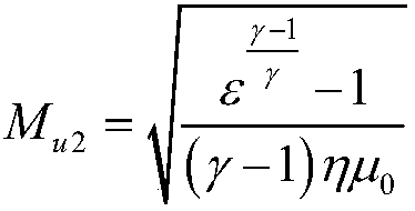
[0074] 5) Calculate the machine Mach number M according to formula (2) u2 =1.65659

[0075] 6) Assume initial M w1,0 =1.1

[0076] 7) Calculate β according to formula (3) 1s , the final result β 1s =45.33

[0077] 8) Calculate M according to formula (4) w1 , the final result M w1...


PUM


Abstract

A method of calculating centrifugal impeller pre-swirl entry enthalpy rise coefficient based on maximum flow coefficient comprises: determining design requirements of a centrifugal impeller; giving acharacteristic constant of a fluid medium and a geometric constant of the centrifugal impeller; calculating outlet tangential speed ratio of the centrifugal impeller; setting initial enthalpy rise coefficient; calculating machine Mach number; setting initial relative Mach number of a centrifugal impeller inlet wheel cover; calculating relative axial flow angle of the centrifugal impeller inlet wheel cover; calculating relative Mach number of the centrifugal impeller inlet wheel cover; judging a relative error between the relative Mach number of the centrifugal impeller inlet wheel cover and aset initial relative Mach number of the centrifugal impeller inlet wheel cover is less than a set value; calculating a ratio of the diameter of the centrifugal impeller inlet wheel cover to the diameter of a centrifugal impeller outlet; calculating enthalpy rise coefficient; judging a relative error between the enthalpy rise coefficient and a set initial enthalpy rise coefficient is less than a set value. The method is capable of quickly and accurately calculating enthalpy rise coefficient of a high-flow centrifugal impeller under any pre-swirl entry angle; the centrifugal impeller manufactured has high flow and compact structure.

Description

technical field [0001] The invention relates to a method for calculating the enthalpy-rise coefficient of an arbitrary pre-rotation inlet angle of a centrifugal impeller. In particular, it relates to a method for calculating the enthalpy rise coefficient of the pre-swirled air of a centrifugal impeller based on the maximum flow coefficient. Background technique [0002] Centrifugal compressors are widely used in aero-engines, ground gas turbines, automobile and ship turbochargers, petrochemical compressors, and play an irreplaceable role in the fields of national defense and civil industry. Centrifugal impeller is the core component of centrifugal compressor, and its accurate thermodynamic calculation and design method is a key technology. Accurate calculation of centrifugal impeller enthalpy coefficient is the basis for breaking through this key technology. For a centrifugal impeller with a given machine Mach number, there is a quantitative relationship between the enthal...

Claims


Application Information

Patent Timeline
Patent Type & Authority Applications(China)
IPC IPC(8): F04D29/28G06F17/50
CPCF04D29/284G06F30/17
Inventor 李孝检刘正先
Owner TIANJIN UNIV
Learn More