
Multi-station mold positioning device

A positioning device and multi-station technology, applied in the field of mold manufacturing, can solve the problems of inaccurate workpiece positioning, difficulty in ensuring mold accuracy, and high cost of use, and achieve the effects of high qualified rate of finished products, guaranteed machining accuracy, and reliable machining accuracy

Active Publication Date: 2018-09-14
深圳市益华诚模具有限公司
View PDF10 Cites 2 Cited by
  • Summary
  • Abstract
  • Description
  • Claims
  • Application Information

AI Technical Summary

Problems solved by technology

Ordinary positioning mechanism for drawing and forming molds, especially parts with deep forming depth and large curvature, during production or debugging, due to inaccurate workpiece positioning, it is difficult to ensure the accuracy of the mold, resulting in high scrap rate, production high cost
At the same time, the structure of the mold is mostly special-shaped parts, and the commonly used positioning mechanism can only adapt to the production of a single type of mold, and even the different positioning surfaces of the special-shaped mold cannot be well adapted. face positioning
For more complicated molds that require multi-working surface processing, the combination of multiple positioning mechanisms is used in the prior art. The structure of the production equipment itself is complicated, and the cost of use is relatively high. The adjustment, positioning and disassembly are time-consuming and laborious, the production cost is very high, and the production efficiency is extremely low

Method used


Image

  • Multi-station mold positioning device
  • Multi-station mold positioning device
  • Multi-station mold positioning device

Examples


Embodiment Construction

[0029] It should be noted that, in the case of no conflict, the embodiments of the present invention and the features in the embodiments can be combined with each other.

[0030] Specific embodiments of the invention will be described in detail below.

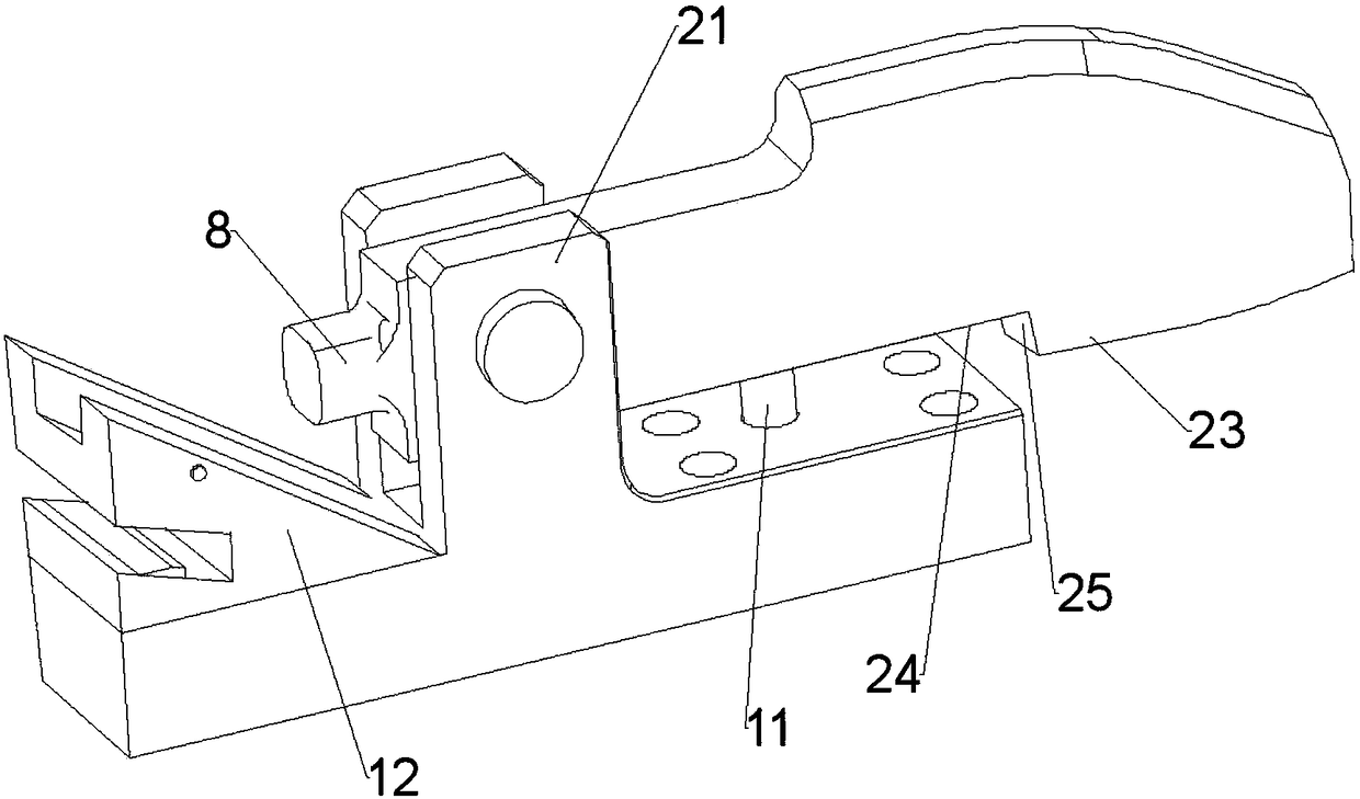
[0031] A multi-station mold positioning device, such as Figures 1 to 6 As shown, it includes the base 1 and the positioning mechanism on the base 1; one end of the base is provided with a diagonal brace structure corresponding to the positioning mechanism, and the other end is provided with a horizontal limit structure corresponding to the positioning mechanism; it should be noted that, in order to facilitate the installation of the device The installation is fixed. According to the actual working conditions, corresponding installation holes can be set on the base, and the base can be fixed on the corresponding position of the equipment by means of bolts and other connecting parts.

[0032] The positioning mechanism includes ...


PUM

PropertyMeasurementUnit
Roughnessaaaaaaaaaa
Surface roughnessaaaaaaaaaa

Abstract

The invention provides a multi-station mold positioning device. The multi-station mold positioning device comprises a pedestal and a positioning mechanism; an inclined strut structure is arranged on the pedestal; a horizontal limiting structure is arranged at the other end of the pedestal; the positioning mechanism comprises a positioning plate; the positioning plate comprises a stop part and a positioning part positioned at the lower part of the stop part; a first stop surface is arranged on one side, facing the inclined strut structure, of the stop part; a second stop surface is arranged onone side, facing the horizontal limiting structure, of the stop part; the positioning part is hinged to a bracket of the pedestal through a hinged shaft; a positioning fork is arranged at the lower end of the positioning part; a positioning hole is formed in the positioning base; a first positioning piece is arranged on one side, facing the inclined strut structure, of the positioning part; and asecond positioning piece is arranged on one side, facing the horizontal limiting structure, of the positioning part. The multi-station mold positioning device can provide a plurality of positioning modes and can adapt to various working conditions; and the multi-station mold positioning device is simple in structure and convenient and quick in operation, so the production efficiency can be improved effectively, foundation is laid for high-precision mold processing, the qualification rate of finished products is high and the processing precision is guaranteed reliably.

Description

technical field [0001] The invention belongs to the technical field of mold production and manufacturing, and in particular relates to a multi-station mold positioning device. Background technique [0002] In the production process of the stamping die, the positioning of the plate and the loading and unloading link play a vital role in ensuring the product qualification rate and production efficiency. Reasonable panel positioning is the prerequisite for obtaining qualified panels, and a reasonable design of the loading and unloading device can effectively improve production efficiency and panel appearance quality. Ordinary positioning mechanism for drawing and forming molds, especially parts with deep forming depth and large curvature, during production or debugging, due to inaccurate workpiece positioning, it is difficult to ensure the accuracy of the mold, resulting in high scrap rate, production The cost is high. At the same time, the structure of the mold is mostly spe...

Claims


Application Information

Patent Timeline
IPC IPC(8): B23Q3/18
CPCB23Q3/18
Inventor 刘文霞
Owner 深圳市益华诚模具有限公司
Learn More