


Quick Research
Generate reliable direction feasibility study reports for your R&D in just a few steps.

Technical Q&A
Discover and master advanced knowledge NOW. Basics, ideas, possibilities, all at once.

Find Solutions
As an expert in R&D theories, this can generate solutions to your technical problems instantly.

Evaluate Feasibility
Analyze your overall solution with one click, know your potential R&D risks in advance.

Monitor Landscape
Get weekly tech updates, stay abreast of the latest tech innovations and key insights.
Method and device for correcting non-uniformity of infrared detector
An infrared detector and non-uniformity technology, applied in the field of infrared detectors, can solve the problems of low calibration efficiency, waste of human and material resources, and calibration accuracy difficult to meet high-precision application requirements, so as to improve efficiency and reduce waste of human resources Effect
- Summary
- Abstract
- Description
- Claims
- Application Information
AI Technical Summary
Problems solved by technology
Method used
Image

Examples
Embodiment Construction
[0039] The non-uniformity correction device of the embodiment of the present invention and the method for correcting the non-uniformity of an infrared detector using the device will be described in detail below with reference to the accompanying drawings.
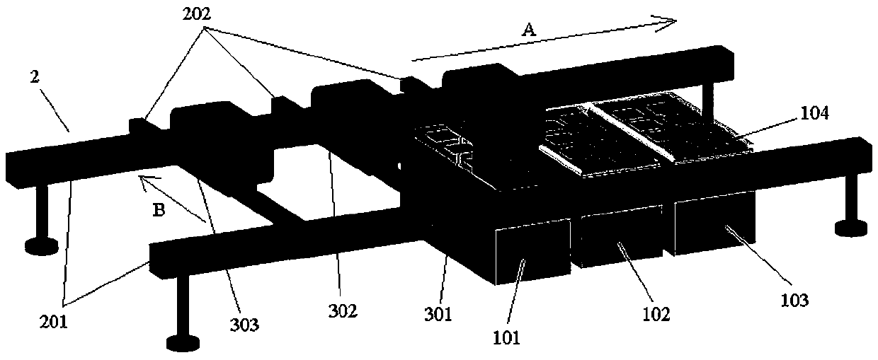
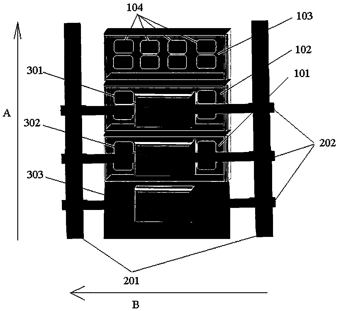
[0040] refer to figure 1 with figure 2 , in one embodiment of the present invention, a device for correcting the non-uniformity of the infrared detector may include a plurality of thermostats (for example, figure 1 with figure 2 101, 102 and 103 in), displacement motor platforms (for example, figure 1 with figure 2 2 in ) and multiple boldfaces (eg, figure 1 with figure 2 301, 302 and 303 in ).
[0041] The plurality of thermostats can be along a first direction (for example, figure 1 with figure 2 Arranged in the direction indicated by the arrow A in). Each incubator houses multiple infrared detector test setups (e.g., figure 1 with figure 2 104 in ). The plurality of infrared detector testing devices are...
PUM
 Abstract
Description
Claims
Application Information
 - R&D Engineer
- R&D Manager
- IP Professional
- Industry Leading Data Capabilities
- Powerful AI technology
- Patent DNA Extraction
Browse by: Latest US Patents, China's latest patents, Technical Efficacy Thesaurus, Application Domain, Technology Topic, Popular Technical Reports.
© 2024 PatSnap. All rights reserved.Legal|Privacy policy|Modern Slavery Act Transparency Statement|Sitemap|About US| Contact US: help@patsnap.com