Linear motion mechanism

A linear motion and rigid technology, applied in mechanical equipment, transmission devices, friction transmission devices, etc., can solve problems such as affecting transmission accuracy and increasing economic costs, and achieve the effect of reducing costs, saving economic costs, and having a simple shape.

Pending Publication Date: 2018-09-11
SHANGHAI LIONSTEK CO LTD
View PDF7 Cites 0 Cited by
  • Summary
  • Abstract
  • Description
  • Claims
  • Application Information

AI Technical Summary

Problems solved by technology

However, due to slippage between the roller and the guide rail, the transmission accuracy is affected. In order to solve this problem, a magnetic scale or a grating scale is usually used for positioning, but this requires the addition of a closed-loop servo control system, which increases the economic cost of the entire system. up

Method used


Image

  • Linear motion mechanism
  • Linear motion mechanism
  • Linear motion mechanism

Examples


Embodiment Construction

[0030] The following is a detailed description with reference to the drawings and specific embodiments.

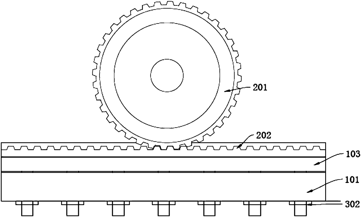
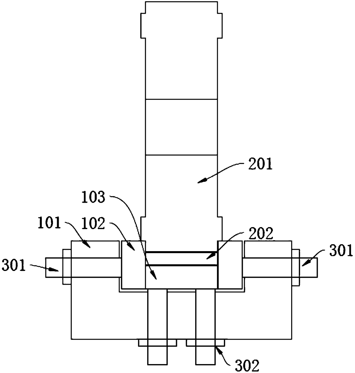
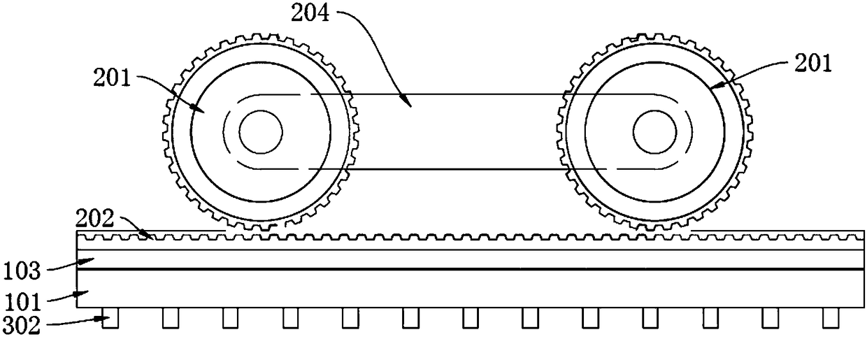
[0031] Such as Figure 1-6 As shown, a linear motion mechanism includes a first U-shaped guide rail support plate 101, a flat synchronous belt 202, and a timing belt wheel 201; wherein the middle of the first U-shaped guide rail support plate 101 is provided with a first groove along the length direction, The flat timing belt 202 is fixed on the bottom surface of the first groove, and the timing belt wheel 201 is engaged with the flat timing belt 202. The installation accuracy can be ensured by the machining accuracy of the first U-shaped guide rail support plate 101, or by Other parts are installed on the U-shaped guide rail support plate 101 for guarantee; the timing belt wheel 201 can be connected to an object such as a mounting frame or a slider, which is used to install parts that require linear motion. In this application, the synchronous belt wheel 201 and the flat sy...


PUM


Abstract

The invention discloses a linear motion mechanism. The linear motion mechanism comprises a first U-shaped guide rail supporting plate, a plane synchronous belt, a synchronous belt wheel, a first rigidbottom plate and first rigid side plates, wherein the first rigid bottom plate and the two first rigid side plates are mounted in a first groove in the first U-shaped guide rail supporting plate; theplane synchronous belt is arranged on the first rigid bottom plate and is engaged with the synchronous belt wheel. The mounting accuracy of the synchronous belt wheel is ensured through the first rigid bottom plate and the first rigid side plates jointly; the first rigid bottom plate and the first rigid side plates are simple and regular in shape, the mounting accuracy is ensured simply by ensuring the parallelism and planeness of a mounting surface, and the machining cost is much lower than that of a traditional sliding rail, therefore, the machining cost is lowered on the whole; and the synchronous belt wheel and the plane synchronous belt cooperate with the moving accuracy of the linear motion system, a locating mechanism or a locating function based servo system is not required to beconfigured independently, so that the economic cost is further reduced.

Description

Technical field [0001] The invention relates to the technical field of linear motion mechanisms, in particular to a linear motion mechanism with high precision and low cost. Background technique [0002] There are many types of mechanisms commonly used in mechanical equipment, and linear motion mechanisms are also common. Among them, linear guide rails and transmission mechanisms are used as a linear motion mechanism and are widely used in the field of mechanical automation. The transmission mechanism includes screw nut pair, rack and pinion pair, belt and pulley transmission, chain and sprocket transmission, etc. Linear guide is a kind of precision part, which has strict requirements on the working environment, and the cost of use and replacement is high; especially for the sliding rail, the machining accuracy of the three faces of the groove is high, and the corresponding machining cost is also high. Screw nut pairs and rack and pinion pairs are relatively high-cost transmissi...

Claims


Application Information

Patent Timeline
Patent Type & Authority Applications(China)
IPC IPC(8): F16H19/02F16H19/06
CPCF16H19/0645F16H2019/0686F16H2019/0613
Inventor 曾继跃郭新星
Owner SHANGHAI LIONSTEK CO LTD
Why Eureka
Try Eureka