
Section bar screw pull-riveting machine

A riveting machine and screw technology, applied to conveyors, conveyor objects, rotary conveyors, etc., can solve the problems of lack of automation in production, failure to meet production requirements, and increase labor intensity of workers

Pending Publication Date: 2018-09-07
广东港古工业自动化有限公司
View PDF0 Cites 2 Cited by
  • Summary
  • Abstract
  • Description
  • Claims
  • Application Information

AI Technical Summary

Problems solved by technology

[0002] Many screws with internal threads need to be fixed on the door and window profiles to facilitate the installation of other door and window components. Because the walls of the profiles are thin, welding will affect the aesthetics. Now the screws are usually fixed by riveting. The current method is to rivet the screws one by one. , laborious, low efficiency, and unable to meet the requirements of mass production, and the current production lacks automation, all of which are directly processed by simple equipment or manual work, which greatly increases the labor intensity of workers. , is the way of survival for many enterprises

Method used


Image

  • Section bar screw pull-riveting machine
  • Section bar screw pull-riveting machine
  • Section bar screw pull-riveting machine

Examples


Embodiment Construction

[0030] The technical solutions of the present invention will be described below in conjunction with the accompanying drawings and embodiments.

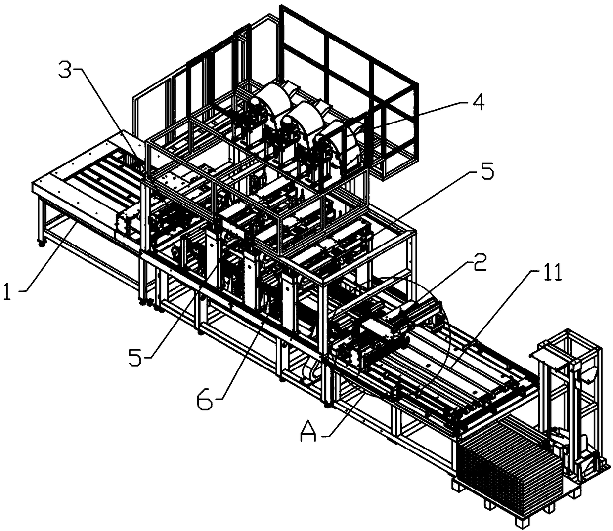
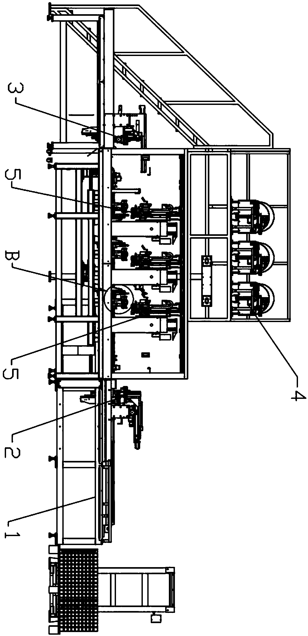
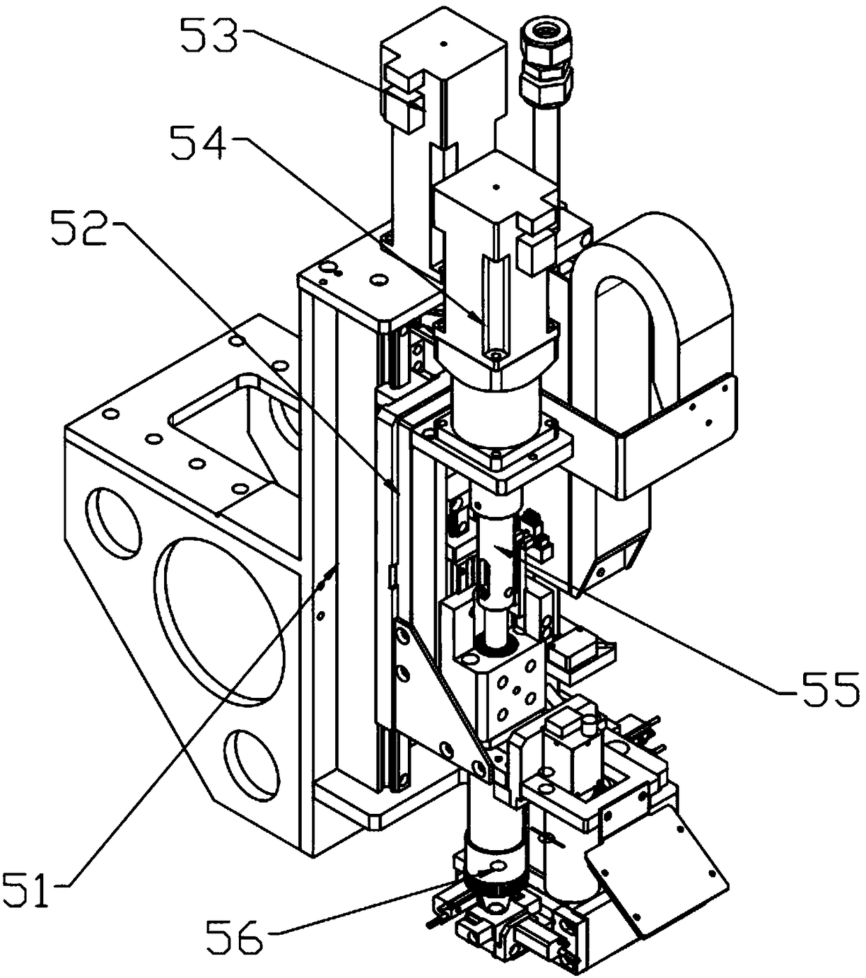
[0031] Such as Figure 1 to Figure 11 As shown, a profile screw riveting machine according to the present invention includes a frame 1, on which a plurality of moving chains 11 are arranged in parallel for conveying profiles, and the frame has two layers, The top layer is provided with a plurality of screw blanking mechanisms 4, and the bottom layer is respectively provided with a loading mechanism 2, a plurality of screw riveting mechanisms 5, a blanking mechanism 3 and a positioning mechanism 6 from right to left, and the positioning mechanism 6 is located on the screw pulling mechanism. Below the riveting mechanism 5, the loading mechanism 2 has the same structure as the unloading mechanism 3; wherein, the screw riveting mechanism 5 includes a riveting frame 51, and the riveting frame 51 is slidingly connected with a Sliding seat ...


PUM


Abstract

The invention provides a section bar screw pull-riveting machine. The section bar screw pull-riveting machine comprises a rack and is characterized in that the rack is provided with multiple moving chains used for conveying section bars in parallel, the rack has two layers, the top layer is provided with multiple screw discharging mechanisms, a feeding mechanism, multiple screw pull-riveting mechanisms, a discharging mechanism and a positioning mechanism are arranged on the bottom layer from right to left, the positioning mechanism is arranged under the screw pull-riveting mechanisms, and thestructure of the feeding mechanism is the same as that of the discharging mechanism. According to the section bar screw pull-riveting machine, continuous operation is achieved through cooperation of the mechanisms, therefore, the machining efficiency is high, machining deviation is not prone to occurring the machine is compact in structure and small in occupation area, unqualified screws are directly pushed out from a material receiving device, and generation of unqualified products is avoided.

Description

technical field [0001] The invention relates to the technical field of riveting, in particular to a profile screw riveting machine. Background technique [0002] Many screws with internal threads need to be fixed on the door and window profiles to facilitate the installation of other door and window components. Because the walls of the profiles are thin, welding will affect the aesthetics. Now the screws are usually fixed by riveting. The current method is to rivet the screws one by one. , laborious, low efficiency, and unable to meet the requirements of mass production, and the current production lacks automation, all of which are directly processed by simple equipment or manual work, which greatly increases the labor intensity of workers. , is the way of survival for many enterprises. Contents of the invention [0003] In view of the above problems, the present invention provides a profile screw riveting machine, which has high processing efficiency, is not easy to be b...

Claims


Application Information

Patent Timeline
Patent Type & Authority Applications(China)
IPC IPC(8): B65G29/00B65G47/90
CPCB65G29/00B65G47/90
Inventor 周剑光
Owner 广东港古工业自动化有限公司
Learn More