A flexible upper limb exoskeleton robot drive system

An exoskeleton robot and drive system technology, which is applied in manipulators, program-controlled manipulators, manufacturing tools, etc., can solve the problems of poor movement flexibility, poor adaptability, and large volume, and achieve large workload, light weight, and reduced volume and quality Effect

Active Publication Date: 2021-03-02
HARBIN INST OF TECH
View PDF4 Cites 0 Cited by
  • Summary
  • Abstract
  • Description
  • Claims
  • Application Information

AI Technical Summary

Problems solved by technology

[0009] The present invention solves the problems of large volume, large mass, poor movement flexibility and poor adaptability in the existing exoskeleton robot drive system, and further provides a flexible upper limb exoskeleton robot drive system

Method used


Image

  • A flexible upper limb exoskeleton robot drive system
  • A flexible upper limb exoskeleton robot drive system
  • A flexible upper limb exoskeleton robot drive system

Examples


specific Embodiment approach 1

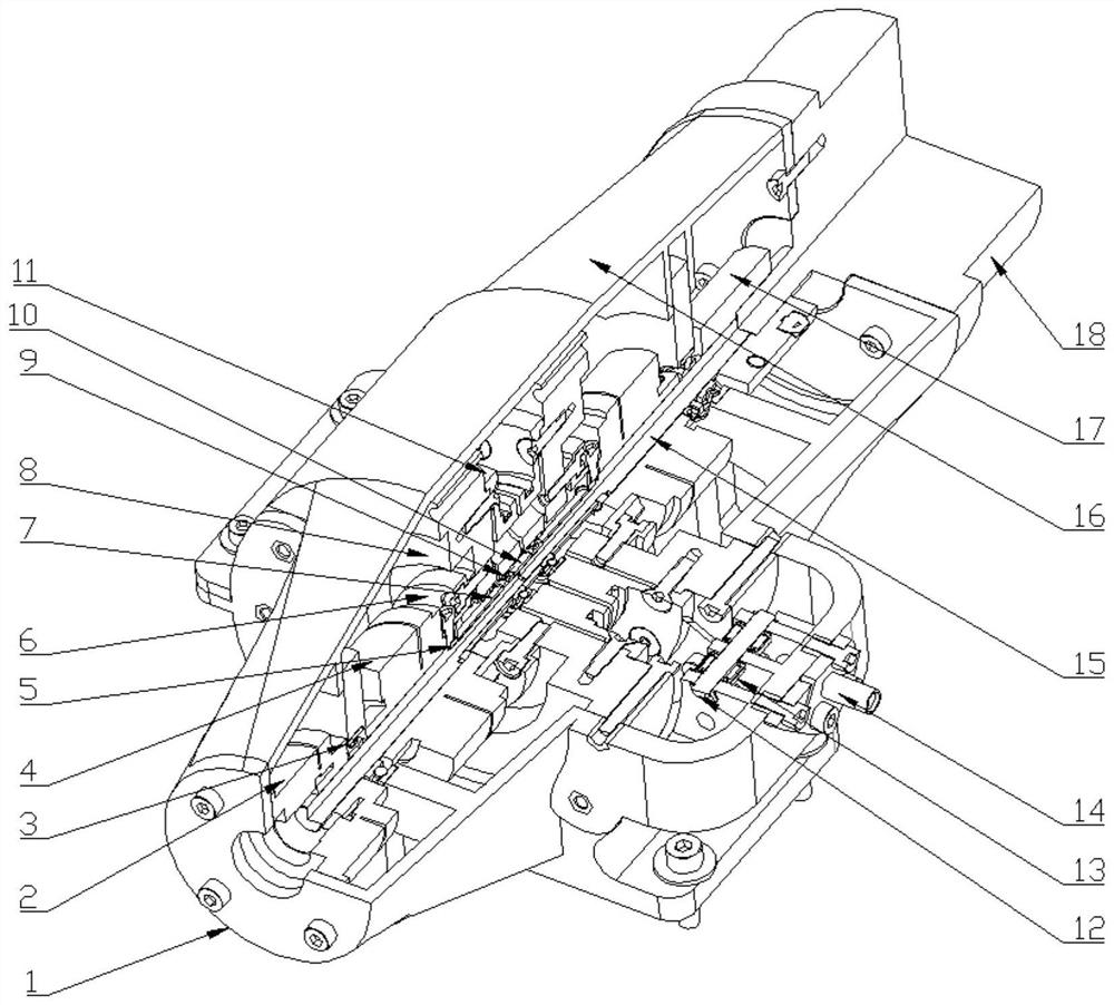
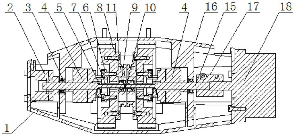
[0034] Specific implementation mode one: as Figure 1-8 As shown, the flexible upper limb exoskeleton robot drive system of this embodiment includes a drive device housing 1, a brake 2, a Bowden wire pretension assembly, a drive device main shaft 15, a drive device housing cover 16, a rigid coupling 17, Brush motor 18, two electromagnetic clutches 4, two connectors 6, two harmonic reducers 8, two wire wheels 11 and two Bowden wires 19; On one end, the output shaft of the brushless motor 18 is affixed to one end of the drive device main shaft 15 through a rigid coupling 17, and the drive device main shaft 15 is installed on the drive device housing 1 through two first deep groove ball bearings 3 to drive The other end of the main shaft 15 of the device is installed on the other end of the housing 1 of the driving device through the brake 2. The electromagnetic clutch 4 includes an armature rotor and an anti-rotation plate. The armature rotor is fixed on the main shaft 15 of the...

specific Embodiment approach 2

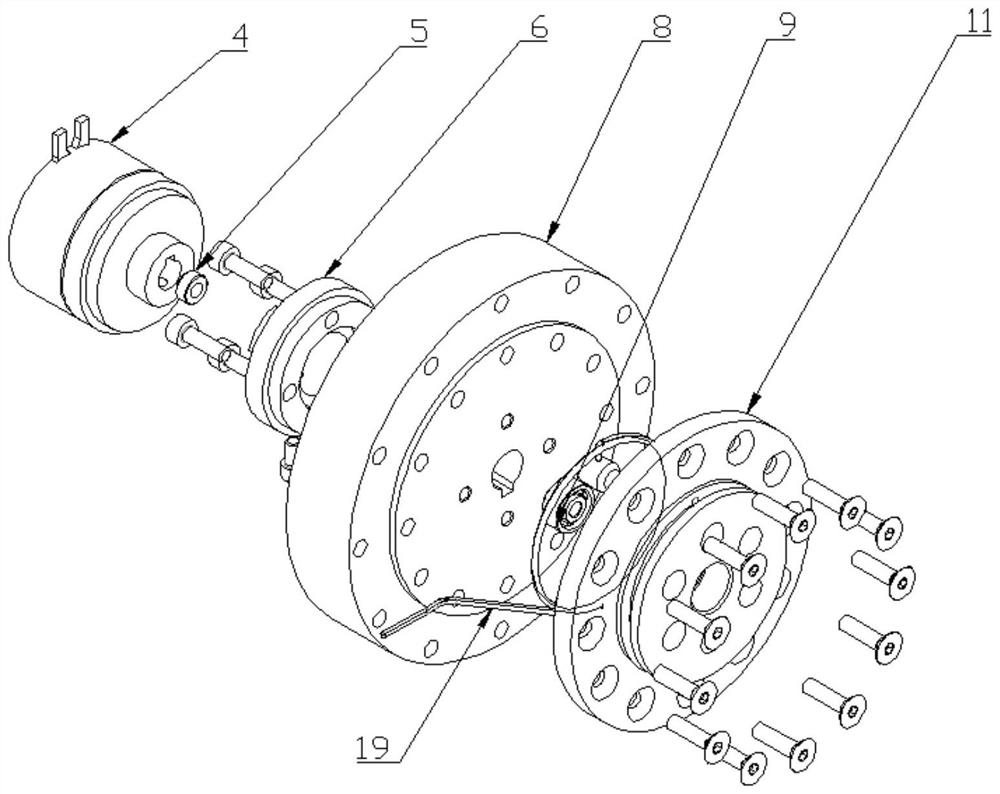
[0043] Specific implementation mode two: as Figure 5 and Figure 6 As shown, the wire wheel 11 in this embodiment is provided with a wire wheel joint slot 11-1 and a wire wheel winding slot 11-2, and the fixed end of the Bowden wire 19 is connected to the wire wheel joint slot 11-1, and each wire A Bowden wire 19 is wound in the wheel winding slot 11-2. With such a design, the Bowden wire 19 can be fixed at the slot 11-1 of the spool joint, and then wound in the spool winding slot 11-2. Other components and connections are the same as those in the first embodiment.

specific Embodiment approach 3

[0044] Specific implementation mode three: as image 3 , Figure 5 and Figure 6 As shown, the wire wheel 11 of this embodiment is provided with a flange, and the flange is uniformly processed with a plurality of shoulder through holes along its circumferential direction. The flange of the wire wheel 11 is fixedly connected to the corresponding harmonic wave by a plurality of bolts. On the steel wheel of speed reducer 8. Such a design facilitates the wire wheel 11 to be fixedly connected to the corresponding steel wheel of the harmonic reducer 8 through bolts. Other compositions and connections are the same as those in Embodiment 1 or 2.


PUM


Abstract

The invention provides a flexible upper-limb exoskeleton robot driving system, and relates to a driving system. By adoption of the flexible upper-limb exoskeleton robot driving system, the problem that an existing exoskeleton robot driving system is large in size, large in mass, poor in movement flexibility and poor in adaptability is solved. A spindle of a driving device is fixedly sleeved with an armature rotor. A rotation stopping plate is clamped at the position of a protrusion of a driving device shell. The spindle of the driving device is formed by two half shafts which are coaxially connected. Each half shaft is sequentially provided with an electromagnetic clutch, a connecting piece, a harmonic reducer and a rope wheel in a penetrating mode. The two rope wheels are arranged adjacently. The rotation stopping plate is clamped at the position of the protrusion in the shell. The armature rotor is fixedly mounted on the spindle of the driving shaft and is connected to flexible hubsof the harmonic reducers through the connecting pieces. Steel wheels of the harmonic reducers are connected to the driving device shell through bolts. Each rope wheel is mounted on the spindle of thedriving device through a third deep groove ball bearing. The rope wheels are connected to the steel wheels of the corresponding harmonic reducers through bolts. The flexible upper-limb exoskeleton robot driving system is applied to a flexible upper-limb exoskeleton robot.

Description

technical field [0001] The invention relates to an exoskeleton robot drive system, in particular to a Bowden line drive system for a flexible upper limb exoskeleton robot. Background technique [0002] With the continuous improvement of people's living standards and the continuous development of modern medical technology, the average life expectancy of the people has been continuously extended. After entering the 21st century, my country's aging population has gradually increased, and the society has gradually entered an aging society. Due to the decline of body functions, the elderly often suffer from functional degeneration such as lack of strength in the limbs. In today's environment where the aging population is increasing, the degeneration of the elderly's physical function should be paid attention to by the society. This will not only improve the quality of life of the elderly, but also reduce the country's pension burden. [0003] Exoskeleton robots can significantl...

Claims


Application Information

Patent Timeline
Patent Type & Authority Patents(China)
IPC IPC(8): B25J9/00B25J9/10
CPCB25J9/0006B25J9/10
Inventor 董为杜志江陈朝峰孙鑫
Owner HARBIN INST OF TECH
Why Eureka
Try Eureka