T-shaped automatic nest box

An egg box, automatic technology, applied in the application, poultry industry, poultry cage or house, etc., can solve the problems of difficult disassembly and maintenance, low space utilization, environmental pollution, etc., and achieve easy installation, disassembly and maintenance, and space utilization. The effect of large and lower production cost

Pending Publication Date: 2018-09-07
HEBI BOLONG ANIMAL HUSBANDRY MACHINERY CO LTD
View PDF0 Cites 2 Cited by
  • Summary
  • Abstract
  • Description
  • Claims
  • Application Information

AI Technical Summary

Problems solved by technology

At present, most chickens are raised in a two-high and one-low feeding mode. Most of the egg-laying boxes are placed at the roots of the walls on both sides of the chicken house, resulting in a narrow egg-laying space. Chickens can only enter from one direction when laying eggs. It is inconvenient to enter and exit, which limits the activity space for chickens to lay eggs, and the ventilation is not smooth, which is easy to cause environmental pollution and cause rapid spread of diseases
In addition, because the chickens tend to stand on the hen house after laying eggs, they need to be forced out, which will frighten the chickens. First, it will affect the egg production rate, and second, it will easily cause the eggs to break and affect the output.
Furthermore, due to the preposition of the egg chute, the space utilization rate is low, which increases the production cost
Also because the fixing methods of the laying box are all tightly fixed on the wall with expansion screws, one is not easy to clean, the joint between the laying box and the wall is easy to accumulate feces, and the environment is polluted; the other is because it is firmly fixed, it is not easy to disassemble and repair

Method used


Image

  • T-shaped automatic nest box
  • T-shaped automatic nest box

Examples


Embodiment Construction

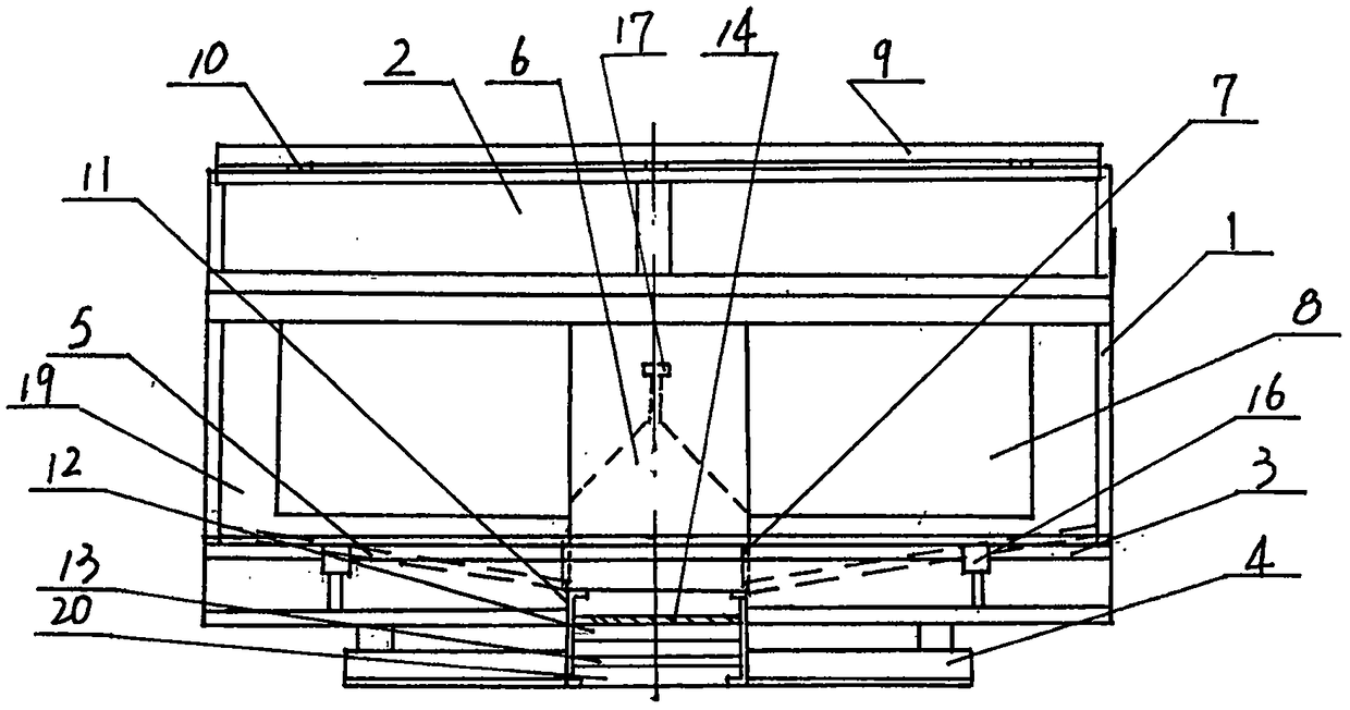
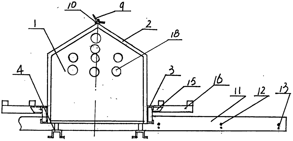
[0008] Such as figure 1 , figure 2 As shown, the inclined top 2 of a T-shaped automatic egg-laying box is fixedly arranged at the upper end of the egg-laying box 1. The egg-laying box 1 is divided into a left and right double-row egg-laying room 19 by an egg channel cover 6 and a partition 17 , The partition plate 17 is fixedly arranged on the upper end of the egg lane trough cover 6, the C-shaped channel steel 3 is fixedly arranged on the front and rear ends of the lower part of the egg-laying box 1, the positioning frame 15 is movably arranged in the slot at both ends of the C-channel steel 3, and the movable station The plate 16 is movably inserted on the positioning frame 15 and is flush with the lower end of the entrance of the laying room 19 of the laying box 1. The anti-chicken movable triangle plate 9 is set on the inclined top 2 of the box with a ball type movable positioning pin 10 At the top, the egg delivery mechanism is inserted into the egg passage groove 20, and...


PUM


Abstract

The invention discloses a T-shaped automatic nest box. A nest box body (1) of the T-shaped automatic nest box is separated into a left-right two-range egg laying room (19) through an egg channel slotcover (6) and a separation plate (17), C-shaped steel channels (3) are fixedly arranged at the front end and the rear end of the lower portion of the nest box body (1), and locating frames (15) are movably arranged in clamping grooves in the two ends of the C-shaped steel channels (3). Movable standing plates (16) are movably inserted into the locating frames (15), and a hen standing preventing movable triangular plate (9) is arranged at the upper top end of a box body inclined top (2) through spherical movable locating pins (10), and an egg conveying mechanism is inserted into an egg channelslot (20). Due to the fact that hens can enter the T-shaped automatic nest box from the front portion and the rear portion, egg laying is convenient, space is saved, and the efficiency is high; the egg conveying mechanism is arranged on the lower middle portion in the box body, the space utilization rate is high, a movable foldable standing plate and the hen standing preventing movable triangularplate are adopted, the breeding hens can safely go in and out of the nest box when laying eggs, a barton is not occupied, and mounting, demounting and repairing are easy.

Description

Technical field: [0001] The invention relates to a T-type automatic laying box suitable for intensive chicken breeding. Background technique: [0002] With the rapid economic development, the poultry breeding industry is gradually modernizing. At present, most chickens use the two-high and one-low rearing mode. The laying boxes are mostly placed at the roots of the walls on both sides of the chicken house, resulting in a narrow laying space. The chickens can only enter from one direction when laying eggs. It is inconvenient to get in and out, which limits the space for chickens to lay eggs, and the ventilation is not smooth, which is easy to cause environmental pollution and cause the rapid spread of diseases. In addition, because chickens tend to stand on the chicken coop after laying eggs, they need to be forced out, which will scare the chickens. One is to affect the egg production rate, and the other is to easily break the eggs and affect the production. Furthermore, becaus...

Claims


Application Information

Patent Timeline
Patent Type & Authority Applications(China)
IPC IPC(8): A01K31/16
CPCA01K31/16
Inventor 张学亮张泽超张慧敏
Owner HEBI BOLONG ANIMAL HUSBANDRY MACHINERY CO LTD
Why Eureka
Try Eureka