
Replacement device used for disconnector spring

A technology of knife switch and spring sleeve, which is applied in the direction of switchgear, electrical components, etc., and can solve the problems of easy release and energy injury

Pending Publication Date: 2018-09-04
GUANGDONG POWER GRID CO LTD +1
View PDF4 Cites 0 Cited by
  • Summary
  • Abstract
  • Description
  • Claims
  • Application Information

AI Technical Summary

Problems solved by technology

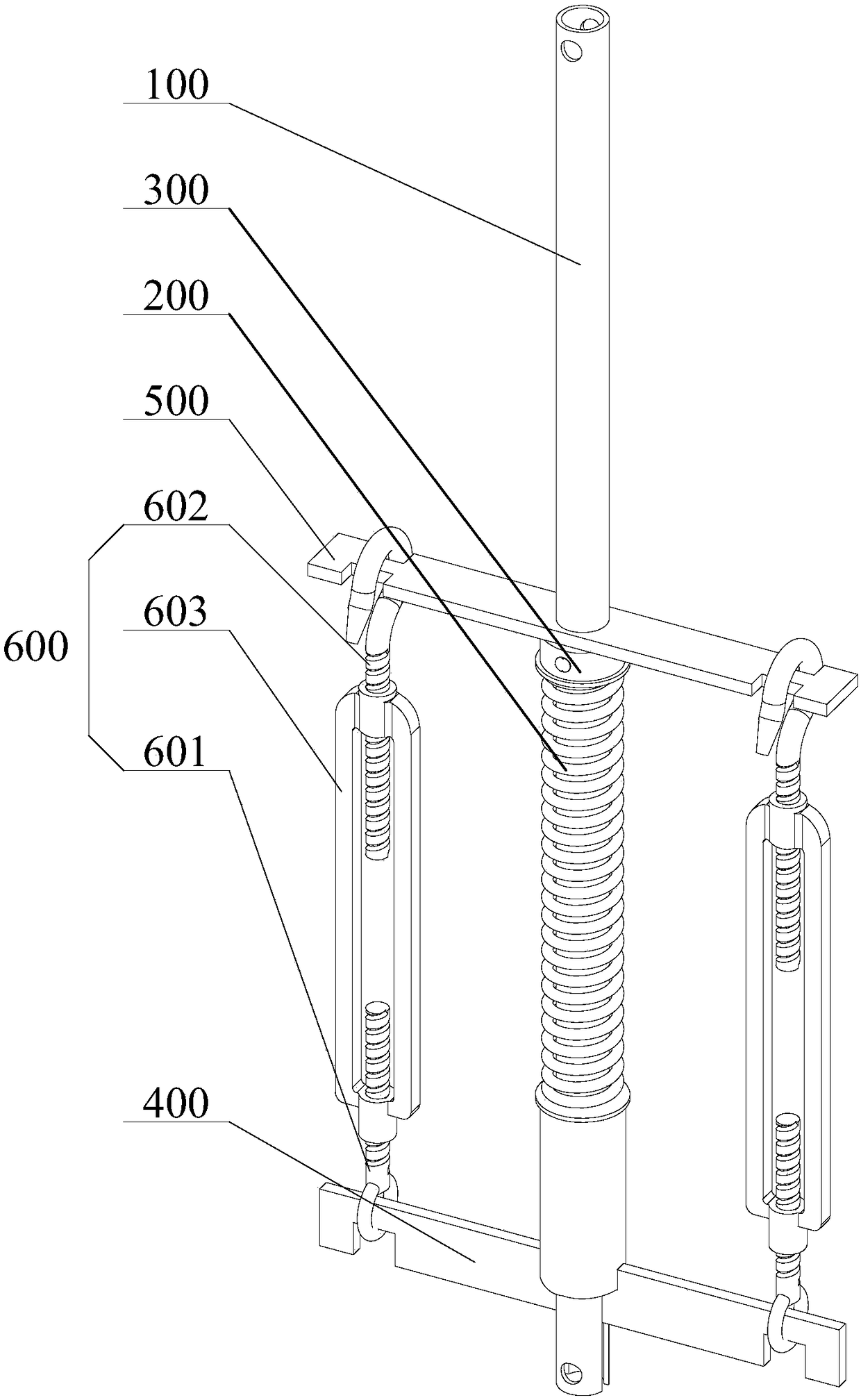
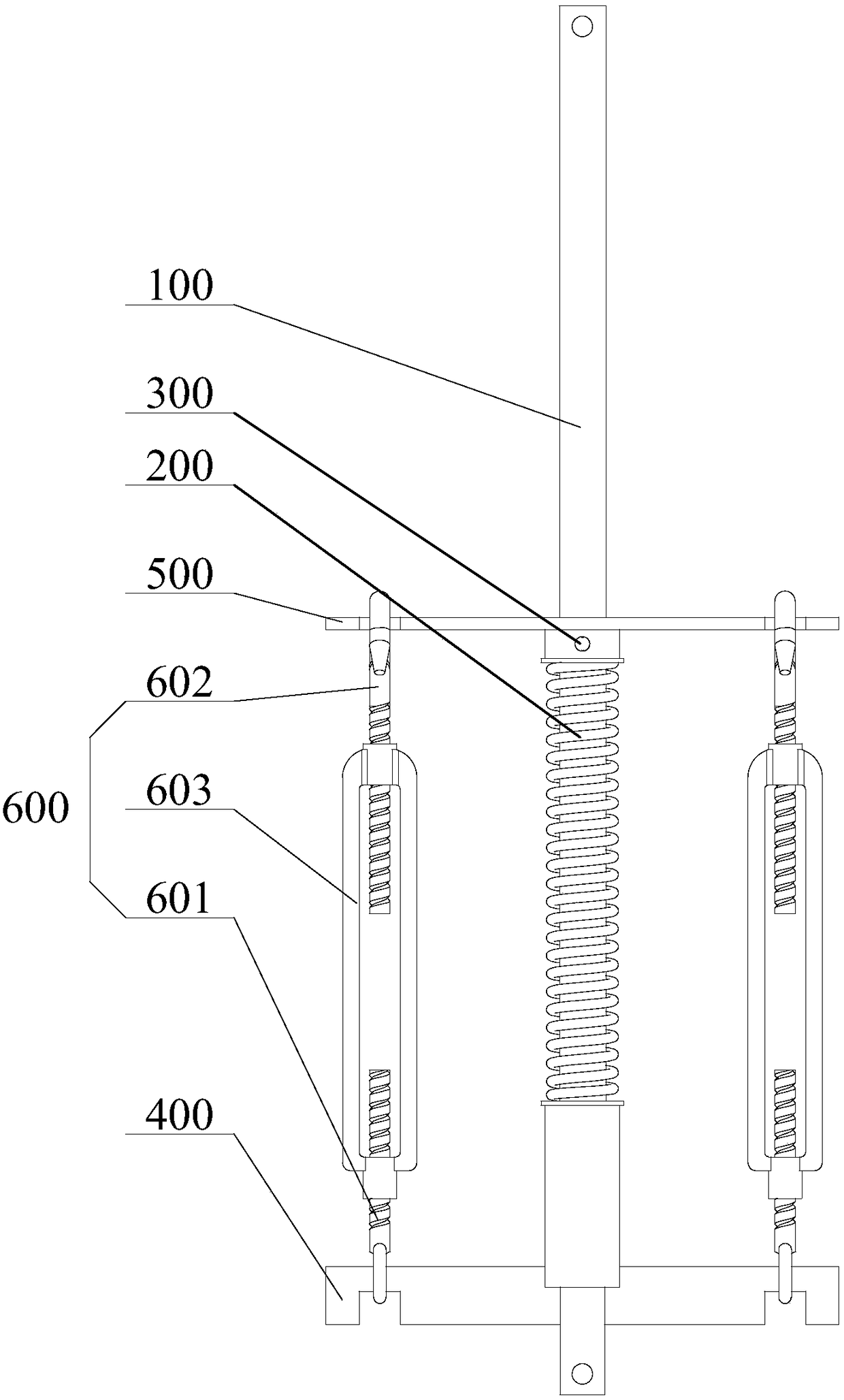
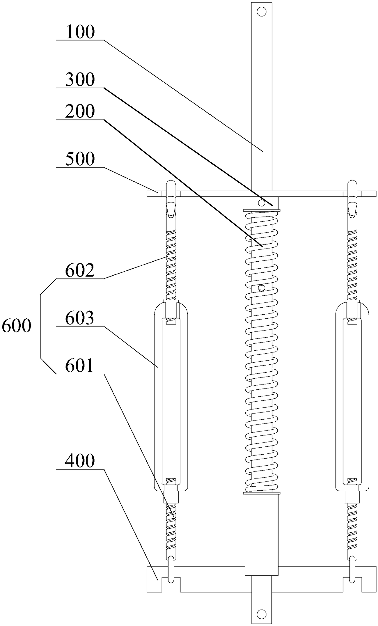
[0004] The purpose of the present invention is to provide a replacement device for the knife switch spring, so as to alleviate the technical problems in the prior art that the knife switch spring is easy to release energy and hurt people when it is disassembled, and the disassembly and assembly is time-consuming and risky.

Method used


Image

  • Replacement device used for disconnector spring
  • Replacement device used for disconnector spring
  • Replacement device used for disconnector spring

Examples


Embodiment Construction

[0028] The technical solutions of the present invention will be clearly and completely described below in conjunction with the accompanying drawings. Apparently, the described embodiments are some of the embodiments of the present invention, but not all of them. Based on the embodiments of the present invention, all other embodiments obtained by persons of ordinary skill in the art without making creative efforts belong to the protection scope of the present invention.

[0029] In the description of the present invention, it should be noted that if the terms "center", "upper", "lower", "left", "right", "vertical", "horizontal", "inner", "outer" appear ", etc., the indicated orientation or positional relationship is based on the orientation or positional relationship shown in the drawings, which is only for the convenience of describing the present invention and simplifying the description, rather than indicating or implying that the referred device or element must have a specif...


PUM


Abstract

The invention provides a replacement device used for a disconnector spring, relating to the technical field of electrical equipment. The replacement device comprises a disconnector rod, a spring and afixing ring, a first fixing seat, a second fixing seat and an adjusting component, wherein one end of the spring is in butt joint with one end of the disconnector rod, and the other end of the springis in butt joint with the fixing ring; the second fixing seat is in butt joint with the fixing ring, two ends of the adjusting component are respectively connected with the first fixing seat and thesecond fixing seat, the second fixing seat can move relative to the disconnector rod by the adjusting component, so as to compress or release the spring by the fixing ring, so that when the spring ofthe disconnector is replaced, elastic energy can be slowly released, and when the spring is mounted, the spring can be slowly compressed; the technical problems in the prior art that energy is easy torelease to hurt people, mounting and dismounting waste time, and risk exists when the disconnector spring is mounted and dismounted are solved; and the replacement device has the advantages of simplestructure, low manufacture cost, simple operation, improvement of working efficiency, reduction of working risk, and increasing of the productivity effect of social enterprises.

Description

technical field [0001] The invention relates to the technical field of electric equipment, in particular to a replacement device for a knife switch spring. Background technique [0002] GW16-220 single-column vertical fracture isolating switch is a three-pole outdoor high-voltage electrical appliance for switching 220kV high-voltage lines under no-carrying conditions and electrically isolating the overhauled high-voltage busbars and other electrical equipment from live lines; this type of switch The brake has reliable performance, simple operation and good flow performance, and is unanimously welcomed by people in the same industry, but this knife switch also has some shortcomings. For example, during the long-term use of this type of knife switch, its internal balance, clamping The shortening of the spring stroke results in a smaller torque, which often leads to difficulties in opening and closing, and the pressure of the clamping contacts becomes smaller. Therefore, after ...

Claims


Application Information

Patent Timeline
IPC IPC(8): H02B3/00
CPCH02B3/00
Inventor 何满棠李志钿朱遂松吴树平王金虎樊健斌黄忠和袁志坚
Owner GUANGDONG POWER GRID CO LTD
Learn More