
A rotary switch and measurement method for man-machine adaptability research

A technology of knob switch and measurement method, which is applied in the testing of mechanical components, testing of machine/structural components, electric switches, etc. It can solve problems such as the inability to adjust the size of the knob, the inability to adjust the manual operating force, and the inability to achieve stroke adjustment. Achieve the effects of wide range of use, convenient adjustment and flexible use

Inactive Publication Date: 2020-03-24
BEIJING UNION UNIVERSITY
View PDF1 Cites 0 Cited by
  • Summary
  • Abstract
  • Description
  • Claims
  • Application Information

AI Technical Summary

Problems solved by technology

[0004] In view of the problems existing in the above-mentioned prior art, the patent of the present invention provides a knob switch and a measurement method for man-machine adaptability research, which is used to solve the problems in the prior art that the manual operation force cannot be adjusted, the size of the knob cannot be adjusted, and The technical problem that stroke adjustment cannot be realized, the patented structure of the invention is simple, easy to use, and strong in practicability

Method used


Image

  • A rotary switch and measurement method for man-machine adaptability research
  • A rotary switch and measurement method for man-machine adaptability research
  • A rotary switch and measurement method for man-machine adaptability research

Examples


Embodiment 1

[0036] In order to achieve the above object, the technical scheme adopted by the patent of the present invention is:

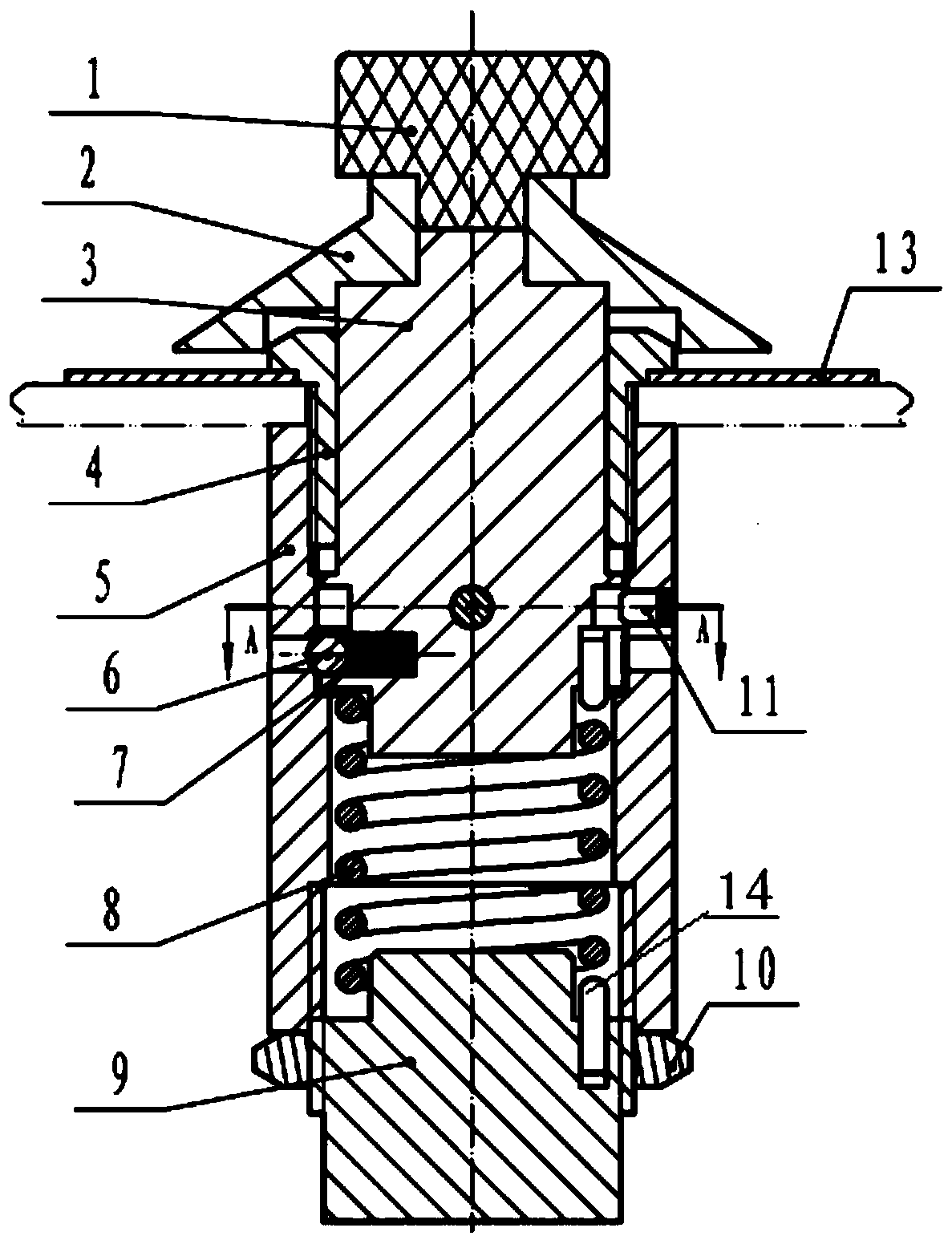
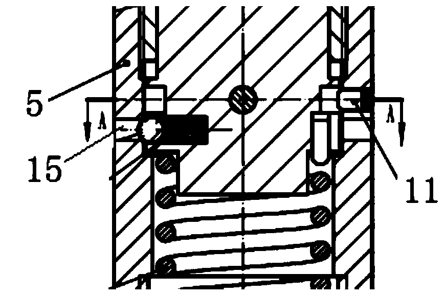
[0037] like Figure 1-Figure 4 As shown, a rotary switch for man-machine adaptability research includes a knob rod 3, the knob rod 3 is provided with a fixed sleeve 4, the outer shell 5 is arranged outside the fixed sleeve 4, the knob rod 3, the fixed sleeve 4 Set concentrically with shell 5.

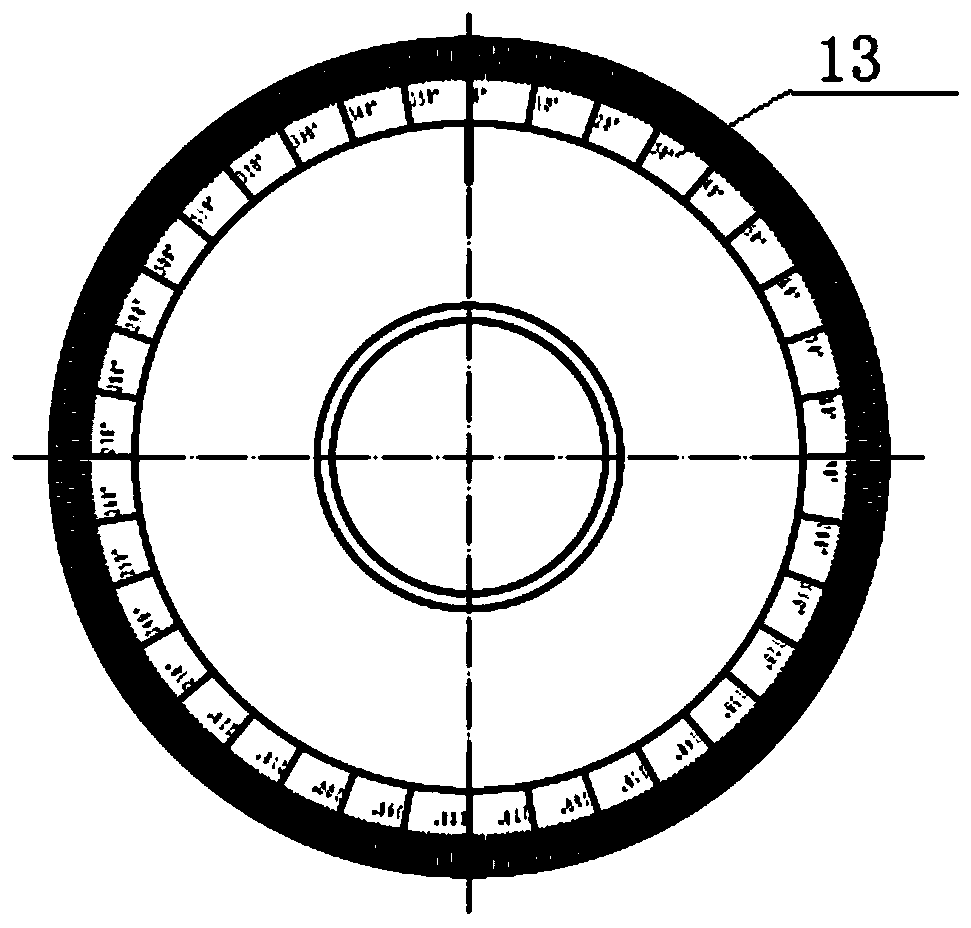
[0038] The upper part of the knob rod 3 is provided with a button cover support 2, and the stroke dial 13 is fixed by the fixed sleeve 4 and the shell 5, and the surface of the stroke dial 13 is evenly distributed with 360° scale marks. A pre-tightening sleeve 9 is provided at the lower part of the knob rod 3 , and an elastic component is provided between the knob rod 3 and the pre-tightening sleeve 9 , and the elastic component is a torsion spring 8 .

[0039] The knob cover 1 is installed on the top of the knob cover support 2, and the longitudinal section of the kn...

Embodiment 2

[0049] A rotary switch used for man-machine adaptability research. The difference from Embodiment 1 is that the limit rod 12 on the knob rod 3 and the positioning pin 11 on the shell 5 are kept on the same plane of the circumference. When adjusting the rotating rod 3, there are initial and limit angles on the circumferential angle of 360°.

Embodiment 3

[0051] A rotary switch used for man-machine adaptability research is different from Embodiment 1 in that the travel dial 13 is located under the button cover support 2 . Keep 0° on the stroke dial 13 and the initial scale mark on the button cover support 2 at the same angular position by adjusting the circumferential position.


PUM


Abstract

The invention discloses a knob switch used for researching human-computer adaptability and a measurement method of the knob switch. The knob switch comprises a knob rod, wherein a fixed sleeve is arranged outside the knob rod, a shell is arranged outside the fixed sleeve, a knob cover support is arranged at an upper part of the knob rod, a range dial is fixed by the fixed sleeve and the shell, a pre-tightening sleeve is arranged at a lower part of the knob rod, and an elastic part is arranged between the knob rod and the pre-tightening sleeve. By the knob switch, a knob cover can be conveniently replaced according to a demand, and the adjustment of the diameter size of a knob control part is achieved; by arranging the range dial, the range dial is arranged below the knob support, and a rotation angle range can be measured on the range dial by an initial positioning line on the knob support after the knob cover is rotated; and the angle positions of uniform angle holes of the knob rod and a ball on the shell can be changed by rotating the knob cover, so that the torsional deformation angles of an upper torsional arm and a lower torsional arm of a torsional spring are changed, and the adjustment of the torque of the knob switch is achieved.

Description

technical field [0001] The patent of the present invention relates to the field of ergonomics and switch technology, and specifically designs a knob switch and a measurement method for man-machine adaptability research. Background technique [0002] Rotary knob switches are widely used in daily life. Factors affecting knob operation include knob force, knob size, and rotation stroke. Therefore, research on the knob force, knob size, and rotation stroke suitable for human operation is the key parameter for rotary switch design. None of the existing rotary switches can realize the adjustment of the knob force and the measurement of the man-machine geometric fit of the knob design parameters. [0003] The patent application number is 201520858136.6, which discloses a knob-type switch. The knob-type switch includes: a command ring, which has a hand feeling structure, and a pressing wheel and a shaft are installed inside, and the shaft is connected and fixed with the knob; the lo...

Claims


Application Information

Patent Timeline
Patent Type & Authority Patents(China)
IPC IPC(8): H01H19/14H01H19/03H01H19/02H01H19/11G01M13/00
CPCG01M13/00H01H19/02H01H19/03H01H19/11H01H19/14
Inventor 杨爱萍呼慧敏张欣
Owner BEIJING UNION UNIVERSITY
Learn More