Gas storage tank
A gas and tank technology, applied in the field of gas storage equipment, can solve the problems of energy consumption, affecting the service life of the gas pump, and the inability to effectively control the working time of the gas pump, achieving high accuracy and good safety
- Summary
- Abstract
- Description
- Claims
- Application Information
AI Technical Summary
Problems solved by technology
Method used
Image
Examples
Embodiment 1
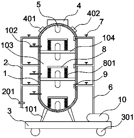
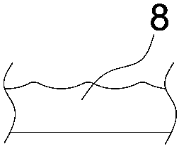
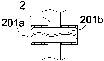
[0014] Such as Figure 1-4 As shown, the gas storage tank includes a tank body 1, the two sides of the tank body 1 are respectively connected with an air intake pipe 6 and an exhaust pipe 2, the air inlet of the air intake pipe 6 is connected with an air pump 10, and the inside of the tank body 1 is divided into A plurality of cavities 103, the two sides of the cavities 103 are respectively connected to the intake pipe 6 and the exhaust pipe 2 and the corresponding cavity 103 is provided with a solenoid valve 7 on the intake pipe 6 and the exhaust pipe 2, and the outlet end of the exhaust pipe 2 is connected to There is a filter 201, and the filter 201 is composed of a housing 201a with a built-in curved filter plate 201b. The present invention divides the inside of the tank body 1 into several cavities 103 through a partition 104, so that each cavity 103 can output gas to the outside respectively. And the input gas, that is, the air pump 10 runs only when the gas inside each ...
Embodiment 2
[0018] When the gas storage tank of the present invention is actually used: the storage tank is placed in various places through the roller 301 at the bottom of the base 3. After the gas storage tank is placed, the control panel 4 controls the start of the air pump 10, and the air pump 10 controls the air pump 10 for each cavity respectively. 103 is inflated, and the pressure in the tank body 1 is increased so that the push plate 8 is pressed down and contacts the button 5 on the lower wall of the cavity 103 so that the solenoid valve 7 on the intake pipe 6 closes the intake of the intake pipe 6. When the tank body When the gas in 1 is released through the exhaust pipe 2 and the gas pressure in the tank 1 gradually drops, the originally compressed spring 801 is slowly released and contacts the button 5 on the upper wall of the cavity 1 to close the solenoid valve on the exhaust pipe 2 7. Prevent the gas from continuing to be discharged, and then the air pump 10 will work to fil...
PUM
 Abstract
Description
Claims
Application Information
 - R&D
- Intellectual Property
- Life Sciences
- Materials
- Tech Scout
- Unparalleled Data Quality
- Higher Quality Content
- 60% Fewer Hallucinations
Browse by: Latest US Patents, China's latest patents, Technical Efficacy Thesaurus, Application Domain, Technology Topic, Popular Technical Reports.
© 2025 PatSnap. All rights reserved.Legal|Privacy policy|Modern Slavery Act Transparency Statement|Sitemap|About US| Contact US: help@patsnap.com


