Pneumatic pressing machine

A pneumatic and frame technology, applied in the direction of stamping machines, presses, manufacturing tools, etc., can solve the problems of low efficiency, workpiece falling off, etc., and achieve the effects of convenient use, reducing falling off, and reducing inertia

Pending Publication Date: 2018-09-04
KUNSHAN RUI PU XIN COATING MACHINERY
View PDF10 Cites 0 Cited by
  • Summary
  • Abstract
  • Description
  • Claims
  • Application Information

AI Technical Summary

Problems solved by technology

In the past, the workpiece was loaded manually, the efficiency was low and the workpiece often fell off the fixture

Method used


Image

  • Pneumatic pressing machine
  • Pneumatic pressing machine

Examples


Embodiment

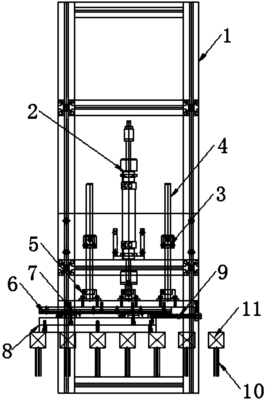
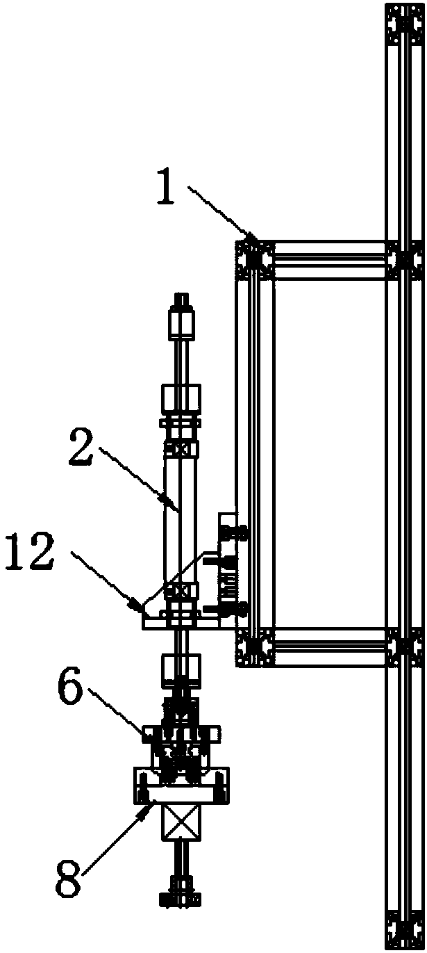
[0018] Such as Figure 1-2 As shown, a pneumatic pressing machine includes a frame 1, a cylinder mounting frame 12 is fixed on the frame 1, and a reciprocating lifting cylinder 2 is fixedly installed on the frame 1 through the cylinder mounting frame 12, so The end of the piston rod at one end of the reciprocating lifting cylinder 2 is fixedly connected with the linear slide rod 6 through a positioning joint 5. The frame 1 on both sides of the reciprocating lifting cylinder 2 is fixed with a guide rod positioning sleeve 3, and the A guide rod 4 is movably inserted in the guide rod positioning sleeve 3, and the bottom end of the guide rod 4 is fixedly connected with the linear sliding rod 6 through the positioning joint 5, and the linear sliding rod 6 is connected through the sliding rod on it. The rail is slidably equipped with a slider 7, and the linear slide bar 6 is slidably connected with a pressing plate 8 through the slider 7, the bottom of the pressing plate 8 is in clo...


PUM


Abstract

The invention discloses a pneumatic pressing machine. The pneumatic pressing machine comprises a rack, wherein an air cylinder mounting frame is fixedly arranged on the rack; the rack is fixedly equipped with a reciprocating lifting air cylinder; the end part of a piston rod of one end of the reciprocating lifting air cylinder is fixedly connected with a linear slide rod through a positioning joint; guide rod positioning sleeves are fixedly arranged on rack portions at the two sides of the reciprocating lifting air cylinder; guide rods are movably inserted into the guide rod positioning sleeves; the bottom ends of the guide rods are fixedly connected with a linear slide rod through positioning joints; the linear slide rod is equipped with a slide block through a slide rail on the linear slide rod in a sliding mode; and the linear slide rod is connected with a pressing plate through the slide block in the sliding mode. The pneumatic pressing machine is compact in structure; the pressingplate is fixed through the guide rod, horizontality of the pressing plate is guaranteed, the reciprocating lifting air cylinder is compact in structure, and is light in weight, light weight and reliability of a pressed workpiece are guaranteed, the linear slide rod and a buffer spring fix the pressing plate and reduce inertia when a line body operates, workpiece loading efficiency is improved, and workpiece drop is also reduced.

Description

technical field [0001] The invention relates to a pressing machine, in particular to a pneumatic pressing machine, which belongs to the technical field of mechanical devices. Background technique [0002] Due to the small size and large quantity of accessories such as cosmetics and automotive interior parts. In the past, the workpiece was loaded manually, the efficiency was low and the workpiece often fell off from the jig. Contents of the invention [0003] The technical problem to be solved by the present invention is to overcome the defects of the prior art and provide a pneumatic pressing machine. The guide rod not only fixes the pressing plate, but also ensures the horizontality of the pressing plate. The reciprocating lifting cylinder is compact in structure and light in weight. To ensure the lightness and reliability of the pressing workpiece, the linear slide bar and the buffer spring not only fix the pressing plate, but also reduce the inertia of the line body du...

Claims


Application Information

Patent Timeline
Patent Type & Authority Applications(China)
IPC IPC(8): B30B1/32B30B15/00
CPCB30B1/32B30B15/00B30B15/0076
Inventor 石淦刘登
Owner KUNSHAN RUI PU XIN COATING MACHINERY
Why Eureka
Try Eureka