Grouting machine

A grouting machine and grouting technology, applied in the direction of supply device, liquid cleaning method, clay preparation device, etc., can solve the problems such as not easy to block materials, achieve not easy to block materials, good use effect, improve use effect and service life Effect

Pending Publication Date: 2018-09-04
GUANGXI HONGFA HEAVY IND MACHINE
View PDF6 Cites 1 Cited by
  • Summary
  • Abstract
  • Description
  • Claims
  • Application Information

AI Technical Summary

Problems solved by technology

[0002] The vertical wall panel forming machine adopts top injection, which requires that the injection machine must be compact in size, large in capacity, fast in injection speed, and not easy to block the material, so as to meet the height requirements of most workshops, especially for cement slurry containing EPS. For grouting with benzene particle rubber, the problem of blocking and cleaning after long-term use is particularly prominent

Method used


Image

  • Grouting machine
  • Grouting machine
  • Grouting machine

Examples


specific Embodiment 1

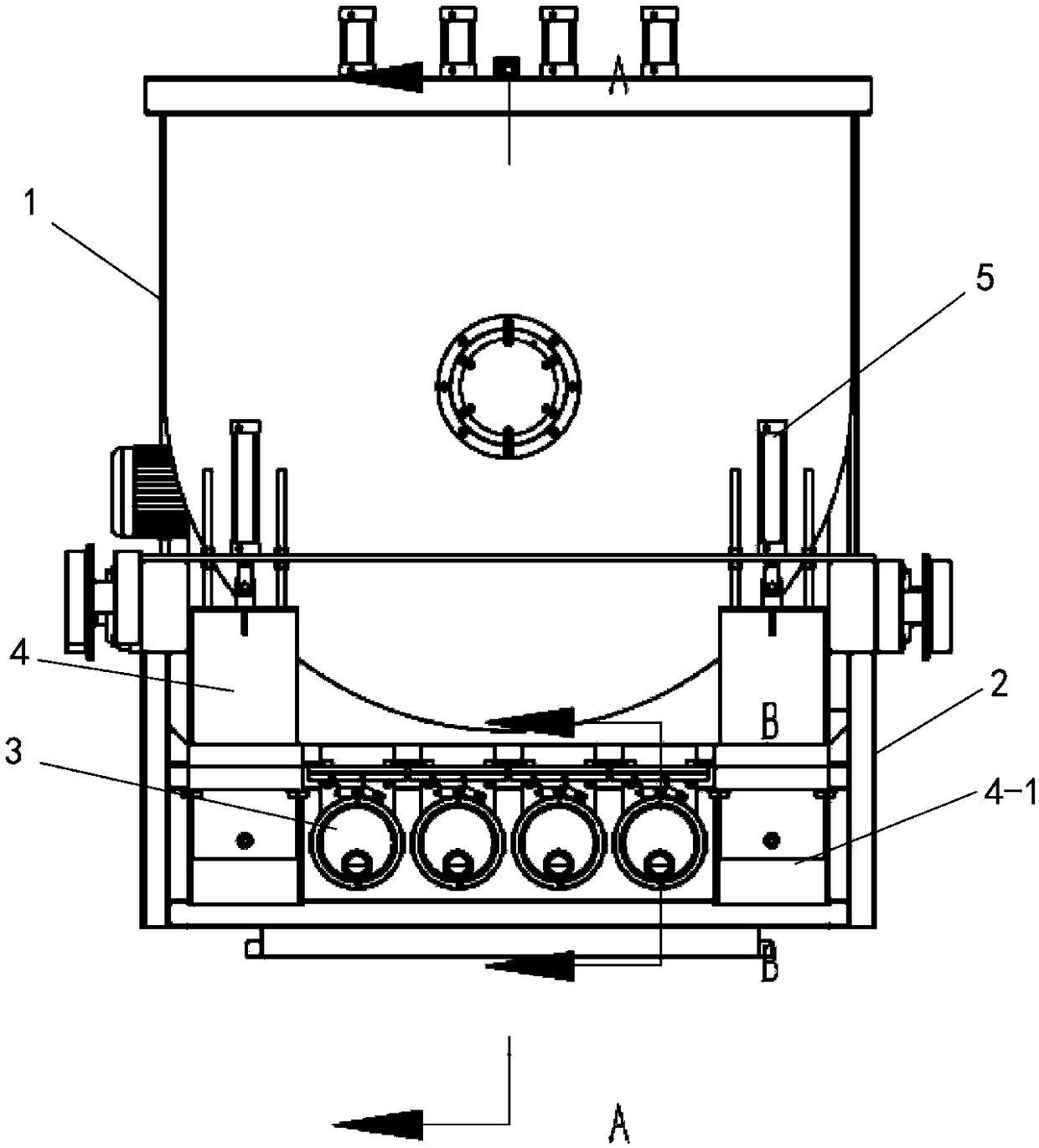
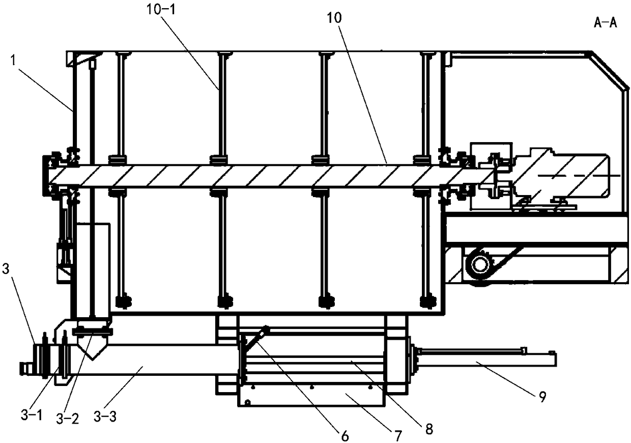
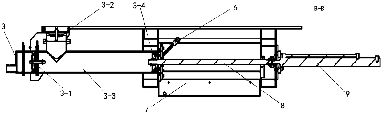
[0015] like Figure 1~3 As shown, a grouting machine includes a mixing tank 1, a grouting cleaning assembly and two free grouting pipelines 4, and the grouting cleaning assembly is distributed on the lower bracket 2 of the grouting machine; the grouting cleaning assembly includes Four grouting pumps 3, cleaning components and four sets of grouting pump driving components; the front part of the grouting pump 3 is provided with a grout inlet and a grout outlet; the grout inlet is provided with a one-way valve 3-2; The slurry outlet is provided with a one-way valve 3-1; the slurry inlet is connected to the bottom of the stirring box 1; the cleaning assembly includes a water pump and a cleaning tank 7; the cleaning tank 7 is distributed in the Below the back of the grouting pump 3; the water inlet of the water pump is distributed in the cleaning tank 7, so that the water in the cleaning tank 7 is circulated; cavity, the water in the cleaning tank 7 is sprayed into the inner cavit...

specific Embodiment 2

[0017] The difference between this embodiment and Embodiment 1 is that the drive assembly of the grouting pump is a drive structure using a drive motor and a crank connecting rod assembly; the drive motor is combined with the grouting pump 3 through the crank connecting rod assembly The piston rod provides reciprocating driving force for the grouting pump 3 .


PUM


Abstract

The invention discloses a grouting machine. The grouting machine comprises a stirring box and a grouting cleaning assembly. The grouting cleaning assembly comprises grouting pumps, a cleaning assemblyand grouting pump drive assemblies. A grout inlet and a grout outlet are formed in the front portion of each grouting pump, wherein the grout inlet and the grout outlet are provided with one-way valves, and the grout inlet communicates with the stirring box. The cleaning assembly comprises water pumps and cleaning grooves, wherein the cleaning grooves are distributed below the positions behind the grouting pumps. Water inlets of the water pumps are distributed in the cleaning grooves. Water spraying ports of the water pumps are aligned with inner cavities of the grouting pumps. Reciprocatingpower is supplied to the grouting pumps through the grouting pump drive assemblies. The grouting machine is high in grouting speed, not prone to blockage, capable of conducting automatic cleaning, high in efficiency and good in usage effect.

Description

technical field [0001] The invention relates to the technical field of construction machinery, in particular to a grouting machine. Background technique [0002] The vertical wall panel forming machine adopts top injection, which requires that the injection machine must be compact in size, large in capacity, fast in injection speed, and not easy to block the material, so as to meet the height requirements of most workshops, especially for cement slurry containing EPS. For grouting with benzene particle rubber, the problems of blocking and cleaning after long-term use are particularly prominent. [0003] The disclosure of the above background technical content is only used to assist in understanding the concept and technical solution of the present invention, and it does not necessarily belong to the prior art of this patent application. If there is no clear evidence that the above content has been disclosed on the filing date of this patent application In some cases, the ab...

Claims


Application Information

Patent Timeline
Patent Type & Authority Applications(China)
IPC IPC(8): B28B13/02B28C5/14B08B3/02
CPCB08B3/02B28B13/02B28C5/14
Inventor 李凤军林初仁潘景昌
Owner GUANGXI HONGFA HEAVY IND MACHINE
Why Eureka
Try Eureka