
Image splicing method, computer device, and display device

An image splicing and display device technology, applied in computing, image enhancement, image analysis and other directions, can solve the problem of slow splicing speed, achieve the effect of fast splicing speed, avoid huge amount of calculation, and simple splicing process

Active Publication Date: 2018-08-31
BOE TECH GRP CO LTD
View PDF9 Cites 13 Cited by
  • Summary
  • Abstract
  • Description
  • Claims
  • Application Information

AI Technical Summary

Problems solved by technology

[0004] Embodiments of the present invention provide an image stitching method, computer equipment, and a display device, which are used to solve the problem of slow stitching speed caused by using a differential algorithm for image stitching

Method used


Image

  • Image splicing method, computer device, and display device
  • Image splicing method, computer device, and display device
  • Image splicing method, computer device, and display device

Examples


Embodiment Construction

[0042] The technical solutions in the embodiments of the present invention will be clearly and completely described below in conjunction with the accompanying drawings in the embodiments of the present invention. Obviously, the described embodiments are only a part of the embodiments of the present invention, rather than all the embodiments. Based on the embodiments of the present invention, all other embodiments obtained by those of ordinary skill in the art without creative work shall fall within the protection scope of the present invention.

[0043] Hereinafter, the terms "first" and "second" are only used for descriptive purposes, and cannot be understood as indicating or implying relative importance or implicitly indicating the number of indicated technical features. Thus, the features defined with "first" and "second" may explicitly or implicitly include one or more of these features. In the description of the embodiments of the present application, unless otherwise specif...


PUM


Abstract

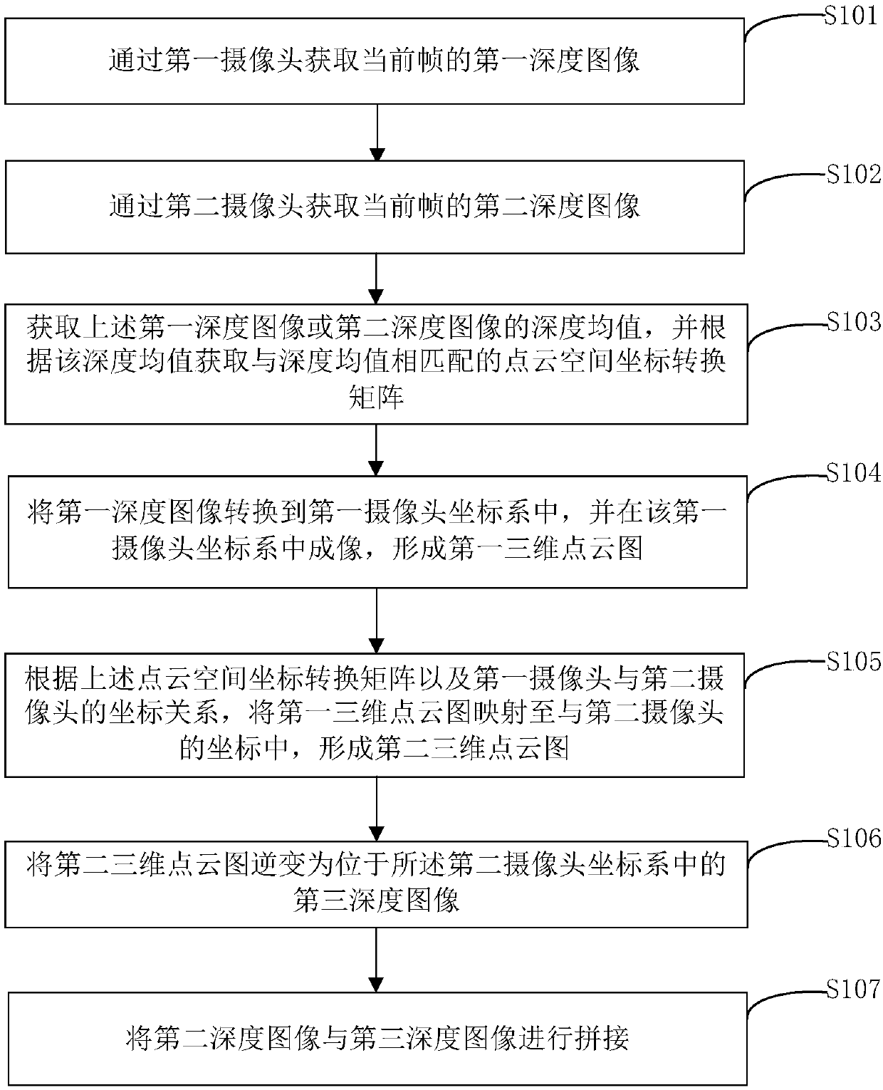
Embodiments of the present invention provide an image splicing method, a computer device, and a display device, and relate to the technical field of display, which is used to solve the problem that the image splicing is performed by using a differential algorithm, resulting in a slow splicing speed. The image splicing method includes steps of: acquiring a first depth image of a current frame by using a first camera; acquiring a second depth image of the current frame by using a second camera; acquiring a depth average of the first depth image or the second depth image, and acquiring a point cloud space coordinate transformation matrix matched with the depth average; converting the first depth image into a first camera coordinate system, and performing imaging in the first camera coordinatesystem to form a first three-dimensional point cloud image; mapping the first three-dimensional point cloud image to in the second camera coordinate system to form a second three-dimensional point cloud image; inverting the second three-dimensional point cloud image into a third depth image located in the second camera coordinate system; and splicing the second depth image with the third depth image.

Description

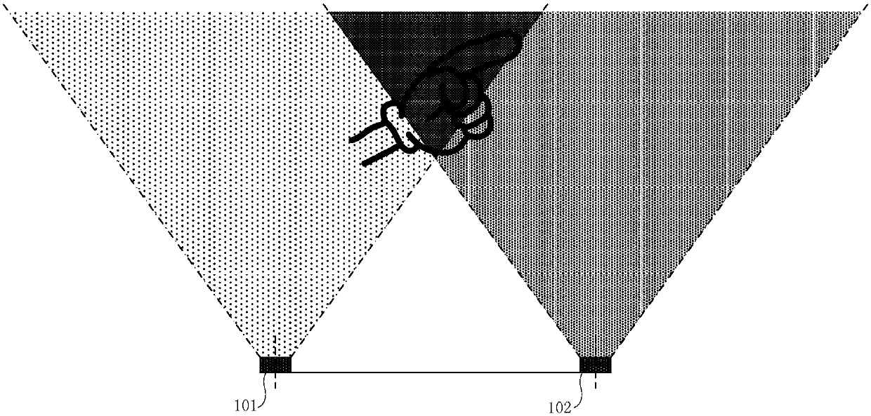
Technical field [0001] The present invention relates to the field of display technology, in particular to an image splicing method, computer equipment and display device. Background technique [0002] At present, gesture interaction uses technologies such as computer graphics to recognize a person's body language, and converts the above body language into control commands to implement device operations. Gesture interaction is a new way of human-computer interaction after the mouse, keyboard and touch screen. [0003] In the process of gesture interaction, it is necessary to collect the user's gesture, and call the control command matching the gesture according to the collected gesture. In the process of collecting gestures, in order to avoid collection blind spots, multiple cameras are usually set to collect gestures. In this case, it is necessary to stitch the images collected by multiple cameras. However, the existing splicing technology requires two images to be spliced ​​to ...

Claims


Application Information

Patent Timeline
IPC IPC(8): G06T3/40G06T5/50G06T7/80
CPCG06T3/4038G06T5/50G06T7/80G06T7/85G06T7/593H04N13/246H04N13/239G06T2207/10048G06T2207/20076H04N2013/0081
Inventor 王鹏鹏王海生丁小梁郑智仁韩艳玲张平
Owner BOE TECH GRP CO LTD
Learn More