
A filter bag pinhole gluing device and gluing method thereof

A glue coating device and filter bag technology, which is applied to the surface coating liquid device, coating, pretreatment surface, etc., can solve the problems of uneven glue edge, unsightly appearance, and difficulty in accuracy, and achieve the glue edge Neat and beautiful, accurate gluing position, and improved work efficiency

Active Publication Date: 2019-07-30
JIANGSU LINGFULONG ENVIRONMENTAL ENG CO LTD
View PDF8 Cites 0 Cited by
  • Summary
  • Abstract
  • Description
  • Claims
  • Application Information

AI Technical Summary

Problems solved by technology

[0005] First, the glue applicator is not designed according to the outline of the seam of the filter bag, and the edges of the glue applied are not neat and unsightly;
[0006] Second, the applied glue protrudes from the stitching surface of the filter bag, the amount of glue used is large and the cost is high;
[0007] Third, the stitching of the filter bag moves left and right, and the glue head must be aligned with the stitching manually, which is difficult to ensure the accuracy of the position;
[0008] Fourth, the running speed of the dispensing machine is unstable, but the glue output speed is constant. When the dispensing machine is running slowly, the amount of glue applied on the stitches will be more, otherwise it will be less, and the delivery volume will be very uneven;
[0009] Fifth, every time the glue in the glue barrel is used up, the dispenser needs to be stopped to add glue to the glue barrel, which is a waste of time
[0010] Sixth, the entire gluing process is in an open environment, and the glue will emit toxic and harmful gases, which will bring great hidden dangers to the health of workers

Method used


Image

  • A filter bag pinhole gluing device and gluing method thereof
  • A filter bag pinhole gluing device and gluing method thereof

Examples


Embodiment 1

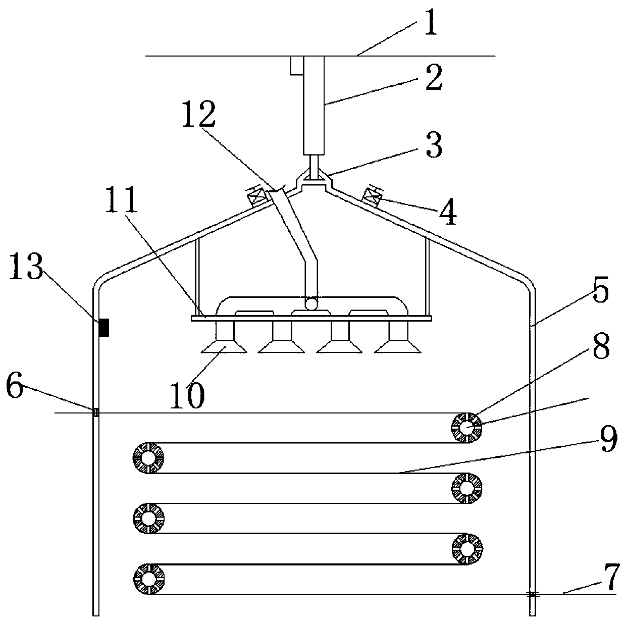
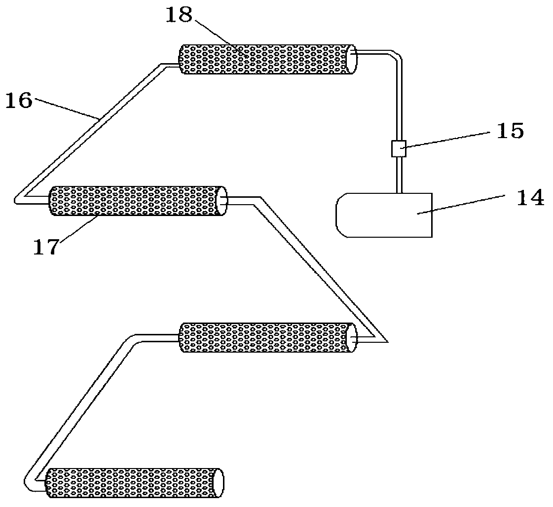
[0052] A filter bag pinhole gluing device of the present invention comprises: a cover shell 5, the cover shell 5 is a semi-closed structure with a lower opening, and a heating device is arranged on the inner wall of the cover shell 5; an electric carriage 1. Set above the cover body 5, the electric carriage 1 is connected to the top of the cover body 5 through the lifting unit 2, and the lifting unit 2 is used to drive the entire cover body 5 to move up and down in the vertical direction ; The filter bag inlet 6 and the filter bag outlet 7 are respectively arranged on the two opposite ends of the cover shell 5, the filter bag inlet 6 and the filter bag outlet 7 are all horizontally arranged, and the width of the filter bag inlet 6 is the same as that of the filter bag outlet 7 The width is adapted to the width of the filter bag 9; 6 electric control rollers are arranged in the cover body, and each electric control roller is arranged alternately in parallel with each other in th...


PUM


Abstract

The invention discloses a filter-bag needle eye gluing device. The device comprises a cover shell, an electric sliding frame; a heat supply device is arranged on the inner wall of the cover shell andat least two electric control rolling shafts; the electric sliding frame is arranged above the cover shell, the electric sliding frame is connected with the top of the cover shell through a first lifting unit, a filter-bag inlet and a filter-bag outlet are formed in two opposite end surfaces of the cover shell correspondingly, the filter-bag inlet and the filter-bag outlet are horizontally arranged, the width of the filter-bag inlet and the width of the filter-bag outlet each are matched with the width of the filter bag, and the filter bag enters cover shell from the filter-bag inlet, and getsout of the cover shell from the filter-bag outlet; all the electric control rolling shafts are parallel to the filter-bag inlet, and are evenly distributed at the two ends, corresponding to the filter-bag inlet and the filter-bag outlet, in the cover shell, and the two ends of each electric control rolling shaft are connected with the inner wall of the cover shell correspondingly. According to the filter-bag needle eye gluing device, the filter bags at different stations can be conveniently dried, moreover, the drying process is completely sealed, and the leakage of poisonous and harmful gasis avoided.

Description

technical field [0001] The invention belongs to the field of mechanical equipment or automation equipment, and in particular relates to a filter bag pinhole gluing device. Background technique [0002] The filter bag is a filter medium made of natural fibers or synthetic fibers. Commonly used materials are cotton, hemp, wool, cocoon silk, asbestos fibers, glass fibers and some synthetic fibers, such as cotton canvas, twill and wool fabric. woolen cloth etc. In a broad sense, filter bags also include metal mesh or filter screens. During the production process of the filter bag, it needs to go through many processes, including the process of applying glue to the pinhole of the filter bag. [0003] In the past, the glue coating and sealing of the filter bag body used a glue dispenser combined with manual control to apply silica gel on the filter bag stitches. The principle is to use the pressure barrel to send the glue in the glue barrel to the glue head. The glue head appli...

Claims


Application Information

Patent Timeline
Patent Type & Authority Patents(China)
IPC IPC(8): B05C15/00B05C13/02B05C5/02B05C11/10B05D3/04
CPCB05C5/027B05C11/1039B05C13/02B05C15/00B05D3/0413
Inventor 朱靓靓朱彦加张瑜李素英张伟付译鋆
Owner JIANGSU LINGFULONG ENVIRONMENTAL ENG CO LTD
Learn More