Light control film and laminated glass
A technology of light-adjusting film and laminated body, applied in the field of light-adjusting film, can solve the problems of reduced liquid crystal orientation, reduced transmittance, etc., and achieve the effects of avoiding the reduction of transmittance, fully stable driving, and avoiding the reduction of appearance quality.
- Summary
- Abstract
- Description
- Claims
- Application Information
AI Technical Summary
Problems solved by technology
Method used
Image
Examples
no. 1 Embodiment approach 〕
[0036] 〔Laminated glass〕
[0037] figure 1 It is a sectional view showing the laminated glass according to the first embodiment of the present invention. This laminated glass 1 is, for example, a laminated glass applied to a window of a vehicle, and is configured by sandwiching a light-adjusting film 10 between plate glasses 2 and 3 via intermediate layers 4 and 5 , respectively. Here, various materials applicable to this type of laminated glass can be widely used for the plate glasses 2 and 3 . In addition, the interlayers 4 and 5 are structures that function as adhesive layers between the light-adjusting film 10 and the flat glasses 2 and 3, and various structures applicable to this type of laminated glass can be widely adopted. It functions as an infrared shielding material.
[0038] With regard to the laminated glass 1, after the interlayers 4, 5 are respectively provided in the flat glasses 2, 3, and laminated with the light-adjusting film 10, heating and pressure are ...
Embodiment 1
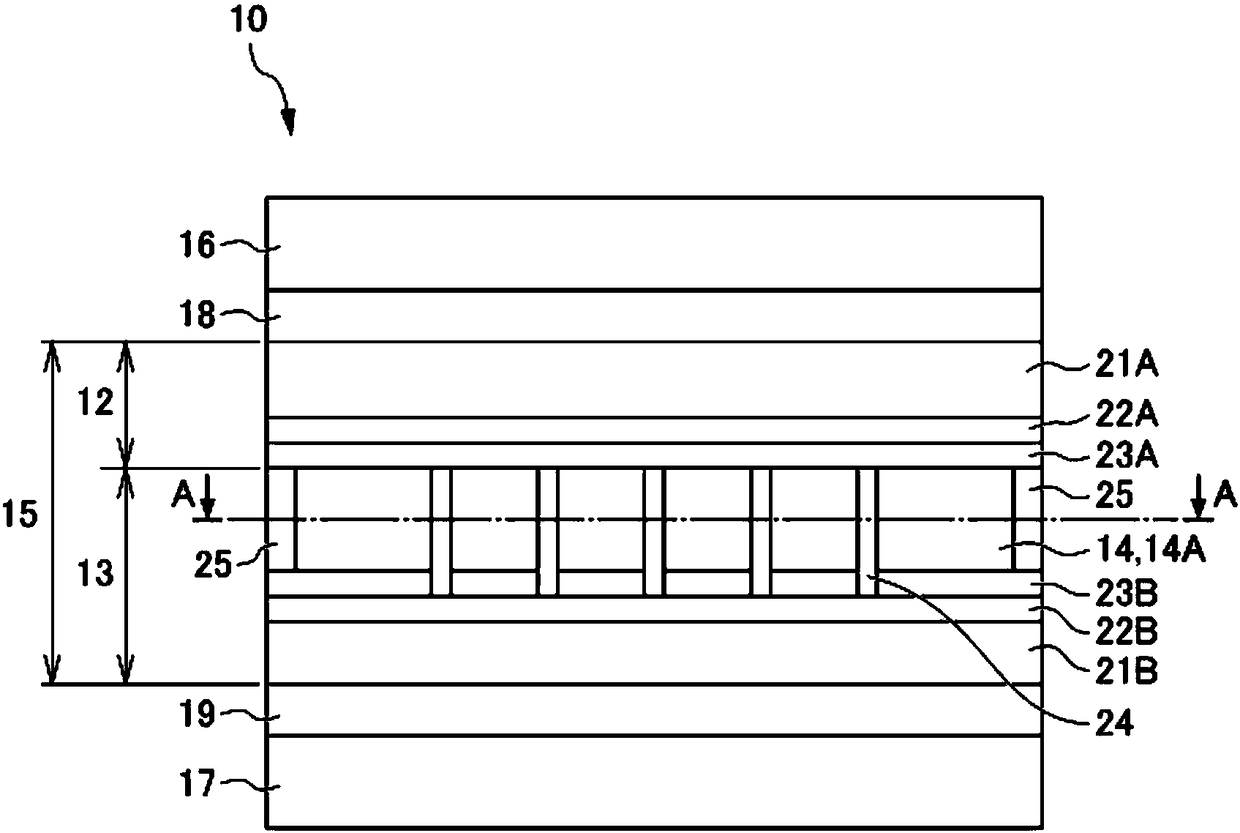
[0072] In Example 1, spacers 24 were arranged with a diameter of 9 μm and a height of 6 μm at a pitch of 110 μm, and the occupancy rate of the spacers was set to 0.5%. In Example 2, the spacers 24 were arranged with a diameter of 27 μm and a height of 6 μm at a pitch of 230 μm, and the occupancy rate of the spacers was set to 1%. In Example 3, the spacers 24 were arranged with a diameter of 28 μm and a height of 6 μm at a pitch of 110 μm, and the occupancy rate of the spacers was set to 5%. In Example 4, spacers 24 were arranged with a diameter of 35 μm and a height of 6 μm at a pitch of 110 μm, and the occupancy rate of the spacers was set to 8%. In Example 5, the spacers 24 were arranged with a diameter of 39 μm and a height of 6 μm at a pitch of 110 μm, and the occupancy rate of the spacers was set to 10%.
[0073] In these Examples 1 to 5, neither collapse of the spacer was observed nor a site where the tip of the spacer 24 penetrated into the opposing surface was found, ...
no. 2 Embodiment approach 〕
[0094] Figure 7 It is a cross-sectional view showing the light-adjusting film 100 of the second embodiment. The second embodiment differs from the first embodiment in that the liquid crystal layer 114 of the second embodiment is a guest-host liquid crystal layer 114 in which guest-host liquid crystal molecules 114A and dichroic dyes are mixed.
[0095] In the second embodiment, the linear polarizing plate can be omitted. The so-called guest-host mode refers to a method in which the dichroic dye 114B is mixed in the guest-host liquid crystal molecules 114A, and the dichroic dye 114B is moved along with the movement of the guest-host liquid crystal molecules 114A, thereby controlling the transmitted light of light. Way.
[0096] in addition, Figure 7 and figure 2 Compared to the same figure except that no linear polarizer is provided, the pair with figure 2 Same component callout as with figure 2 The same reference numerals are used, and explanations are omitted.
[...
PUM
 Abstract
Description
Claims
Application Information
 - R&D
- Intellectual Property
- Life Sciences
- Materials
- Tech Scout
- Unparalleled Data Quality
- Higher Quality Content
- 60% Fewer Hallucinations
Browse by: Latest US Patents, China's latest patents, Technical Efficacy Thesaurus, Application Domain, Technology Topic, Popular Technical Reports.
© 2025 PatSnap. All rights reserved.Legal|Privacy policy|Modern Slavery Act Transparency Statement|Sitemap|About US| Contact US: help@patsnap.com


