
Electronic device

A technology for electronic devices and power supplies, applied in coupling devices, two-part connection devices, circuits, etc., can solve the problems of unstable high-frequency signals, reduced signal integrity, and pass through, and achieve good signal integrity and improve integrity. Effect

Active Publication Date: 2018-08-28
ACER INC
View PDF3 Cites 0 Cited by
  • Summary
  • Abstract
  • Description
  • Claims
  • Application Information

AI Technical Summary

Problems solved by technology

However, the signal terminals of the above-mentioned USB Type C electrical connector are responsible for the function of transmitting high-frequency signals. When high-frequency signals pass through the signal terminals, they are easily interfered by current or signals on other adjacent conductive terminals, resulting in unstable high-frequency signals. ground at the signal terminal through
Therefore, it is easy to cause problems such as high impedance (Impedance), input loss (Input loss) and feedback loss (Returnloss) of signal terminals, resulting in unstable signal transmission operation of the terminal group or reduced efficiency, which in turn leads to reduced signal integrity.

Method used


Image

  • Electronic device
  • Electronic device
  • Electronic device

Examples


Embodiment Construction

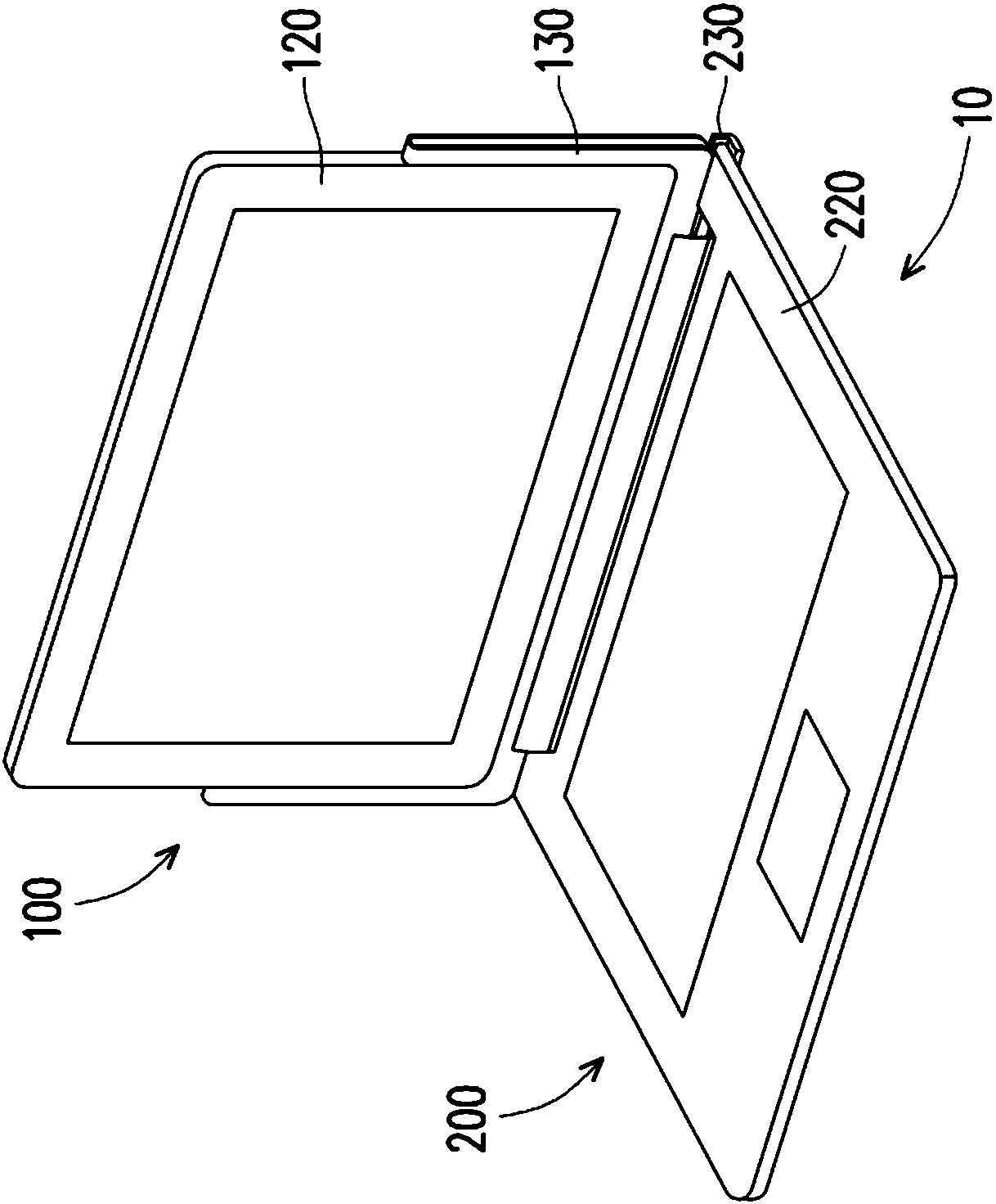
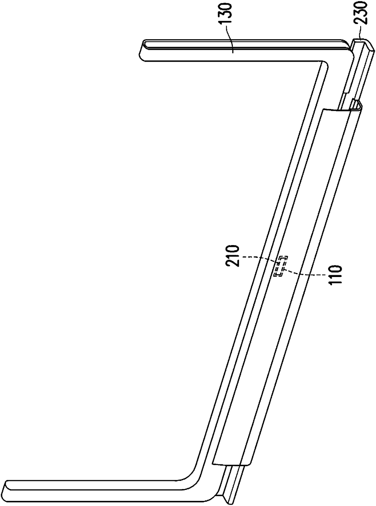
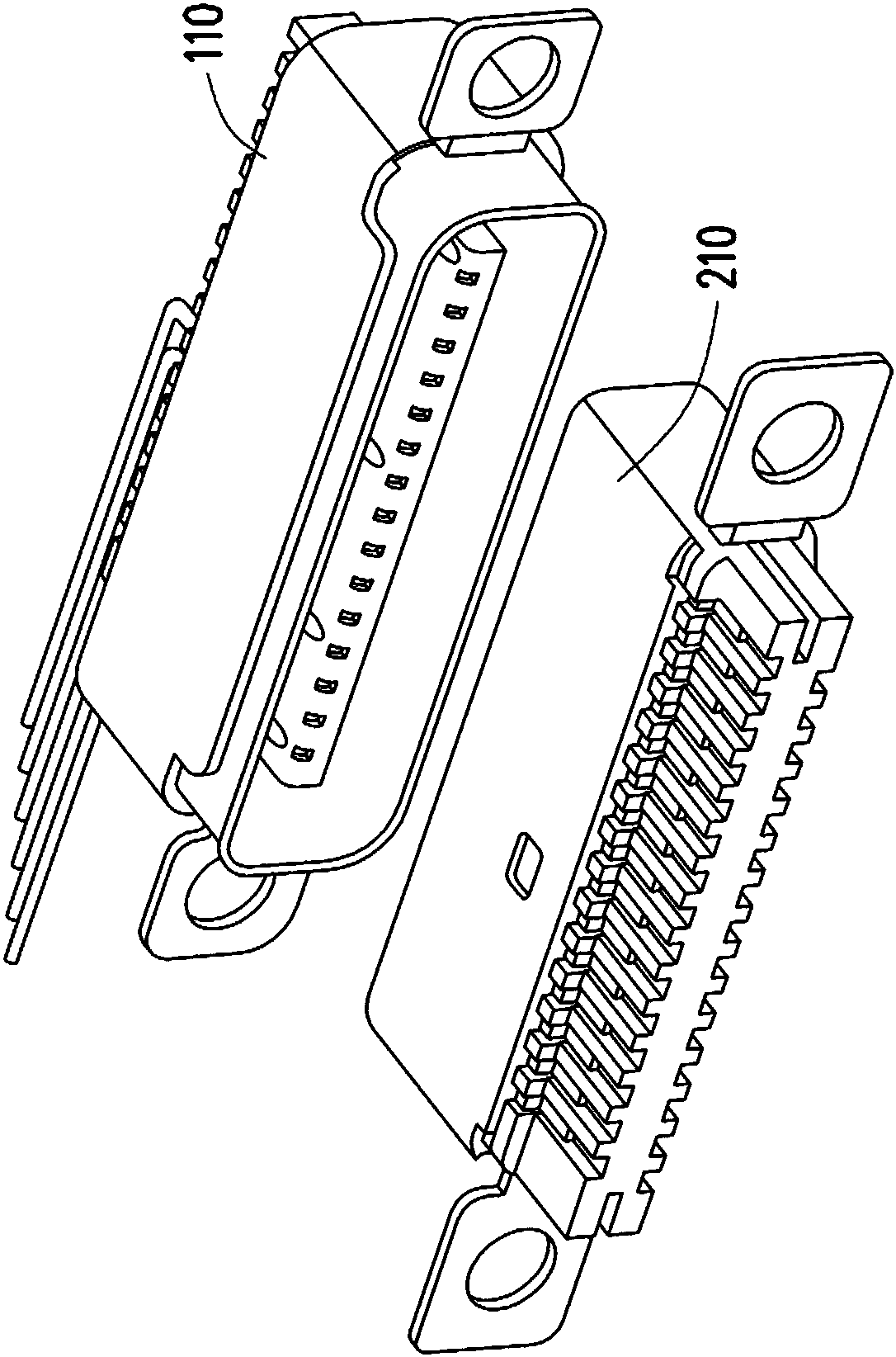
[0057] figure 1 A schematic diagram of an electronic device is shown as an embodiment of the present invention. figure 2 shown as figure 1 A partially enlarged schematic diagram of the monitor and the docking station. image 3 shown as figure 2 A diagram of the first connector on the monitor and the second connector on the docking station. Figure 4 shown as image 3 A schematic cross-sectional view of the first connector and the second connector. Figure 5A shown as Figure 4 A schematic top view of the first connector of . Figure 5B shown as Figure 4 A schematic bottom view of the first connector.

[0058] Please also refer to figure 1 , figure 2 , image 3 , Figure 4 , 5A and Figure 5B , the electronic device 10 of this embodiment includes a display 100 and a docking station 200 . The display 100 includes a first connector 110 , and the first connector 110 includes a first tongue 112 and a plurality of pins 114 . The pins 114 at least include a pair o...


PUM


Abstract

The invention provides an electronic device, which comprises a displayer and an expansion base. The displayer comprises a first connector. The expansion base comprises a second connector. The first connector comprises a first tongue piece and a plurality of pins. The pins at least comprise a pair of differential signal transmission pins and a plurality of grounding pins. The orthographic projection of at least one of the grounding pins on the upper surface of the first tongue piece is located between the differential signal transmission pins. The differential signal transmission pins transmitinformation according with universal serial bus 3.1, lightning 2 or lighting 3 transmission specifications. The second connector comprises a second tongue piece and a plurality of through holes. The through holes at least comprise a pair of differential signal transmission through holes and a plurality of grounding through holes. The differential signal transmission pins and the grounding pins areinserted into the differential signal transmission through holes and the grounding through holes respectively.

Description

technical field [0001] The present invention relates to an electronic device, in particular to an electronic device with a connector capable of performing high-speed signal transmission. Background technique [0002] An electrical connector is a common electronic component on an electronic device, which can be connected to a matching electrical connector on another electronic device, thereby providing signal and power transmission between the two electronic devices. Existing electrical connectors, such as Universal Serial Bus (USB) 3.1 electrical connectors, and the USB 3.1 agreement has added a Type C (Type C) electrical connector specification, in addition to providing 10Gbps ultra-high speed In addition to the high information transmission rate, the volume is light, thin and short, suitable for portable devices such as mobile phones, and the plug interface is symmetrical and can be plugged in forward and reverse, so it will be widely used in various electronic devices. ...

Claims


Application Information

Patent Timeline
IPC IPC(8): H01R24/00H01R13/02
CPCH01R13/02H01R24/00
Inventor 王友史刘志钧李柏毅
Owner ACER INC
Learn More