
Fingerprint identification module and manufacturing method thereof

A technology of fingerprint recognition module and manufacturing method, which is applied in character and pattern recognition, acquisition/organization of fingerprints/palmprints, instruments, etc., and can solve problems such as easy peeling and affecting fingerprint image sensing

Inactive Publication Date: 2018-08-28
PRIMAX ELECTRONICS LTD
View PDF7 Cites 0 Cited by
  • Summary
  • Abstract
  • Description
  • Claims
  • Application Information

AI Technical Summary

Problems solved by technology

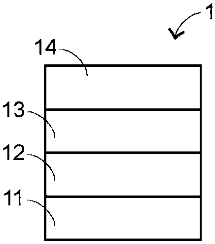
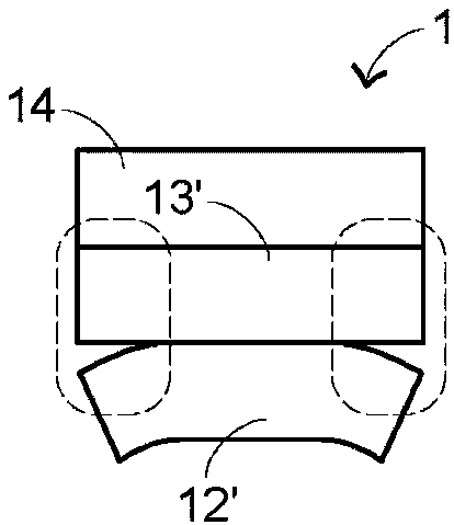
[0004] However, during the manufacturing process of the fingerprint identification module 1, the fingerprint sensing chip 12' often has a warpage when feeding materials, and is used for bonding the cover plate 14 and the fingerprint sensing chip 12 together. Adhesive layer 13' only adopts solid sheet glue, which is as figure 2 As shown, after the fingerprint recognition module 1 that has been manufactured has passed the reliability test, such as after the high temperature and high humidity test or the salt spray test, the peripheral edge of the glued part of the cover plate 14 and the fingerprint sensing chip 12' (such as figure 2 Marked by a dotted circle) prone to peeling
In addition, in the prior art, there is also a method of simply using water glue as the glue layer 13 for the cover plate 14 and the fingerprint sensor chip 12 to be glued together. However, only using water glue for gluing will easily cause the cover plate 14 and fingerprint There are many air bubbles in the middle of the glued part of the sensing chip 12, which affects the sensing of fingerprint images.

Method used


Image

  • Fingerprint identification module and manufacturing method thereof
  • Fingerprint identification module and manufacturing method thereof
  • Fingerprint identification module and manufacturing method thereof

Examples


Embodiment Construction

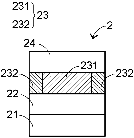
[0053] see image 3 , which is a structural schematic diagram of a preferred embodiment of the fingerprint recognition module of the present invention. The fingerprint identification module 2 includes a substrate 21, a fingerprint sensing element 22 and a cover plate 24. The fingerprint sensing element 22 is arranged on the substrate 21 and is electrically connected to the substrate 21 to obtain power, and the cover plate 24 is located on the fingerprint sensing element 22. and glued to the fingerprint sensing element 22 via an adhesive layer 23, which provides a contact interface between the finger and the fingerprint sensing element 22 and protects the surface of the fingerprint sensing element 22 from being damaged due to multiple touches of the finger, In addition, the cover plate 24 can have a specific color, such as a color consistent with the electronic product (not shown) to which the fingerprint identification module 2 is applied; wherein, when the finger is placed on...


PUM


Abstract

The invention provides a fingerprint identification module and a manufacturing method thereof. The fingerprint identification module comprises a substrate, a fingerprint sensing component and a coverplate, wherein the fingerprint sensing component is arranged on the substrate and electrically connected to the substrate; the cover plate is located above the fingerprint sensing component and is glued with the fingerprint sensing component through a gluing layer; the gluing layer is located between the cover plate and the fingerprint sensing component, and comprises solid glue and liquid glue; and the solid glue is surrounded by the liquid glue. According to the fingerprint identification module provided by the invention, the gluing quality of the cover plate and the fingerprint sensing component of the fingerprint identification module can be improved.

Description

technical field [0001] The present disclosure relates to the technical field of fingerprint identification, in particular, to a fingerprint identification module for identifying a user's identity through fingerprints. Background technique [0002] In recent years, fingerprint identification technology has been applied to various electronic products, allowing users to input their own fingerprints into the electronic products and let the electronic products be archived, and then users can input their own fingerprints through the fingerprint identification module to carry out electronic product authentication. unlock. Using fingerprint identification technology to unlock electronic products is faster and more convenient than the previous unlocking method of manually inputting a password, so it is favored by users, and the demand for the fingerprint identification module 1 is also greatly increased. [0003] see figure 1 , which is a structural conceptual schematic diagram of ...

Claims


Application Information

Patent Timeline
IPC IPC(8): G06K9/00
CPCG06V40/1306
Inventor 徐茂修丁冠堡
Owner PRIMAX ELECTRONICS LTD
Learn More