Transmission
A transmission and lever technology, which is applied to belts/chains/gears, mechanical equipment, transmission devices, etc., can solve the problem that the transmission ratio of the power arm and the resistance arm cannot be adjusted, and achieve the effect of improving continuity
- Summary
- Abstract
- Description
- Claims
- Application Information
AI Technical Summary
Problems solved by technology
Method used
Image
Examples
Embodiment 1
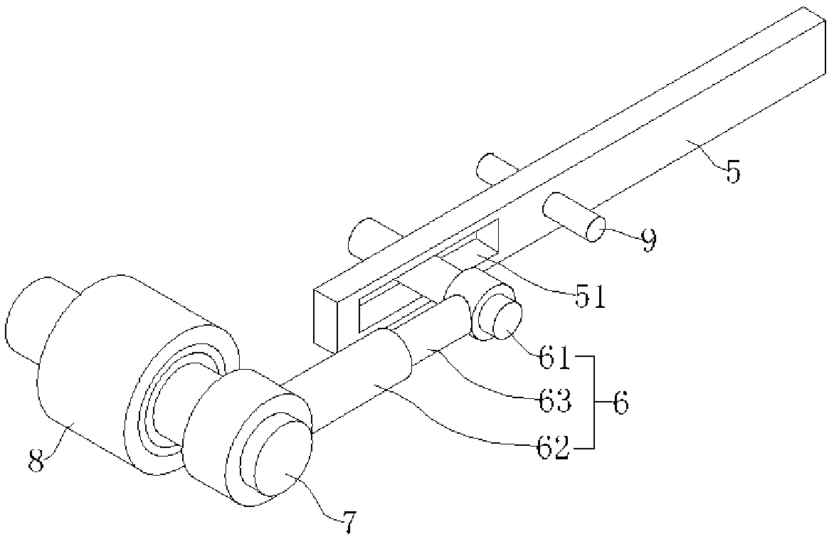
[0060] a transmission such as image 3 As shown, it includes a driving lever 5 and a driven lever 6, and one end of the driven lever 6 is connected with a one-way transmission, and the one-way transmission includes an output shaft 7 fixedly connected to the driven lever 6 and a fixed connection on the output shaft 7. The one-way transmission part adopts one-way bearing 8 (such as the one-way bearing 8 of CSK series), and when the driven lever 6 rotates in one direction around the output shaft 7, the one-way bearing 8 can be driven by the output shaft 7 as a whole Rotate, when the driven lever 6 rotates in another direction, the outer ring of the one-way bearing 8 does not rotate. , when the driven lever 6 does reciprocating swinging motion, it can drive the transmission part to rotate in one direction.
[0061] The end of the driven lever 6 far away from the output shaft 7 is connected with a slider, and the end of the active lever 5 close to the driven lever 6 is provided wi...
Embodiment 2
[0071] A speed changer, the difference from Embodiment 1 is that, as Figure 7 and Figure 8 As shown, the front splicing rod 62 is threadedly connected with the rear splicing rod 63, the length of the driven lever 6 can be rotatably adjusted, and after the length is adjusted, the length of the driven lever 6 is not easy to change during use, and the driven lever 6 The length can be maintained more stably, improving the working reliability of the transmission.
Embodiment 3
[0073] A speed changer, the difference from Embodiment 1 is that, as Figure 9 and Figure 10 As shown, the driven lever 6 also includes a length adjustment rod 64, and the two ends of the length adjustment rod 64 are all provided with threads and are threadedly connected with the front splicing rod 62 and the rear splicing rod 63 respectively by threads, and the threads at the two ends of the length adjustment rod 64 are threaded. On the contrary, when the length adjustment lever 64 is rotated in one direction, the front splicing lever 62 and the rear splicing lever 63 can be made to approach or move away from each other, thereby realizing the function of adjusting the length of the driven lever 6 .
[0074] In this embodiment, without disassembling the driven lever 6, the length adjusting rod 64 can be rotated to adjust the length of the driven lever 6, which is more convenient to adjust.
PUM
 Abstract
Description
Claims
Application Information
 - R&D
- Intellectual Property
- Life Sciences
- Materials
- Tech Scout
- Unparalleled Data Quality
- Higher Quality Content
- 60% Fewer Hallucinations
Browse by: Latest US Patents, China's latest patents, Technical Efficacy Thesaurus, Application Domain, Technology Topic, Popular Technical Reports.
© 2025 PatSnap. All rights reserved.Legal|Privacy policy|Modern Slavery Act Transparency Statement|Sitemap|About US| Contact US: help@patsnap.com


