
Automatic sucking closing mechanism for automobile door lock

A pull-in mechanism, a technology for car door locks, applied in vehicle locks, lock applications, special locking actions, etc., can solve problems such as inconvenience in comfort, high production costs, and high requirements for coordination.

Pending Publication Date: 2018-08-28
河南百川汽车部件有限公司
View PDF5 Cites 7 Cited by
  • Summary
  • Abstract
  • Description
  • Claims
  • Application Information

AI Technical Summary

Problems solved by technology

[0002] With the development of the automobile industry, consumers have higher and higher requirements for the convenience of automobile use. In the traditional automobile door system, in order to make the door close smoothly, a certain external force must be applied to the door. , when the external force is insufficient, the car is likely to be in a half-locked state, and it is necessary to reopen the door and use a greater external force to make it fully locked, which will bring a lot of inconvenience to the comfort of operation
Some high-end cars have an automatic suction mechanism in the door system, which can automatically close the door to a certain extent. However, this mechanism is often too complicated, and the requirements for the cooperation between the internal mechanical structures of the lock body are too high, and the production cost is high.

Method used


Image

  • Automatic sucking closing mechanism for automobile door lock
  • Automatic sucking closing mechanism for automobile door lock
  • Automatic sucking closing mechanism for automobile door lock

Examples


Embodiment Construction

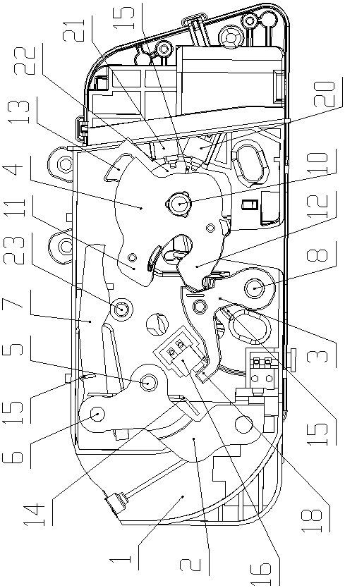
[0020] Such as Figure 1-4 As shown, an automatic suction mechanism for automobile door locks of the present invention includes a housing 1, a drag arm 2, a stop pawl 3 and a clamp 4 are arranged in the case 1, and the stop pawl 3 is located at the drag Between the moving arm 2 and the clamping plate 4, the middle part of the dragging arm 2 is rotatably connected in the housing 1 through the connecting shaft 5, the upper part of the dragging arm 2 is rotatably connected with the drag conversion arm 7 through the hinge shaft 6, and the lower part of the stop pawl 3 It is connected in the housing 1 through the rotation of the intermediate shaft 8. The stop pawl 3 is provided with a slot 9 facing the side of the clamping plate 4. The clamping plate 4 is connected in the housing 1 through the rotating shaft 10. The sides of the clamping plate 4 are fixedly connected at intervals. There are a first clamping head 11 and a second clamping head 12, the side of the clamping plate 4 is ...


PUM


Abstract

An automatic sucking closing mechanism for an automobile door lock comprises a shell. A dragging arm, a locking claw and a clamping plate are arranged in the shell. The locking claw is located betweenthe dragging arm and the clamping plate. The middle of the dragging arm is rotationally connected into the shell through a connecting shaft. A dragging conversion arm is rotationally connected with the upper portion of the dragging arm through a hinge shaft. The lower portion of the locking claw is rotationally connected into the shell through an intermediate shaft. A clamping groove is formed inthe side face, facing the clamping plate, of the locking claw. The clamping plate is rotationally connected into the shell through a rotary shaft. A first clamping head and a second clamping head arefixedly connected with the side portion of the clamping plate in a spaced mode. A check block located on one side of the end of the dragging conversion arm is fixedly connected with the side portionof the clamping plate. A driving device for driving the dragging arm to rotate around the connecting shaft is arranged on one side of the shell. The automatic sucking closing mechanism is simple in structure, safe, reliable, high in practicability and low in manufacturing cost, operation of automatic sucking closing to the full-locking state can be achieved under the partly-locking state of an automobile door, a user does not need to open the automobile door and close the automobile door again, operation is convenient, and the automatic sucking closing mechanism is easy to apply and popularize.

Description

technical field [0001] The invention belongs to the technical field of automobile door locks, in particular to an automatic suction mechanism for automobile door locks. Background technique [0002] With the development of the automobile industry, consumers have higher and higher requirements for the convenience of automobile use. In the traditional automobile door system, in order to make the door close smoothly, a certain external force must be applied to the door. , When the external force is insufficient, the car is likely to be in a half-locked state, and it is necessary to re-open the door and use a greater external force to make it fully locked, which will bring a lot of inconvenience to the comfort of operation. Some high-end cars have an automatic suction mechanism in the door system, which can automatically close the door to a certain extent. However, this mechanism is often too complicated, and the requirements for the cooperation between the internal mechanical s...

Claims


Application Information

Patent Timeline
Patent Type & Authority Applications(China)
IPC IPC(8): E05B77/14E05B79/10E05B79/20E05B81/06E05B81/56
CPCE05B77/14E05B79/10E05B79/20E05B81/06E05B81/56
Inventor 刘尚宁
Owner 河南百川汽车部件有限公司
Learn More