Variable-diameter threaded milling cutter

A variable-diameter thread and milling cutter technology, which is applied in the direction of thread cutting tools, metal processing equipment, tangent devices, etc., can solve the problems of fixed working length, non-variable diameter, inconvenient and fast assembly or disassembly, etc., to achieve connection flexible effects

Inactive Publication Date: 2018-08-28
常州思智行睿精密机械有限公司
View PDF0 Cites 0 Cited by
  • Summary
  • Abstract
  • Description
  • Claims
  • Application Information

AI Technical Summary

Problems solved by technology

[0004] The purpose of the present invention is to solve the problem that the working length of the existing thread milling cutter is fixed when in use, the diameter cannot be changed, and the working length of the milling cutter cannot be adjusted by people. To solve the problem of inconvenient and quick disassembly, a variable-diameter thread milling cutter is proposed

Method used


Image

  • Variable-diameter threaded milling cutter
  • Variable-diameter threaded milling cutter
  • Variable-diameter threaded milling cutter

Examples


Embodiment 1

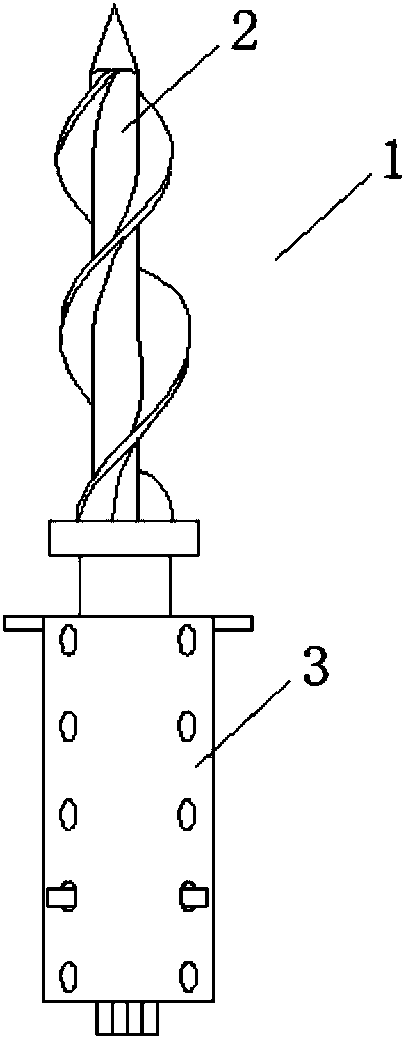
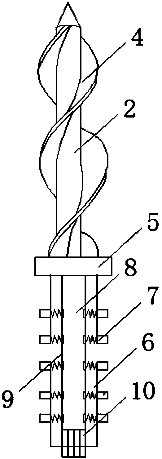
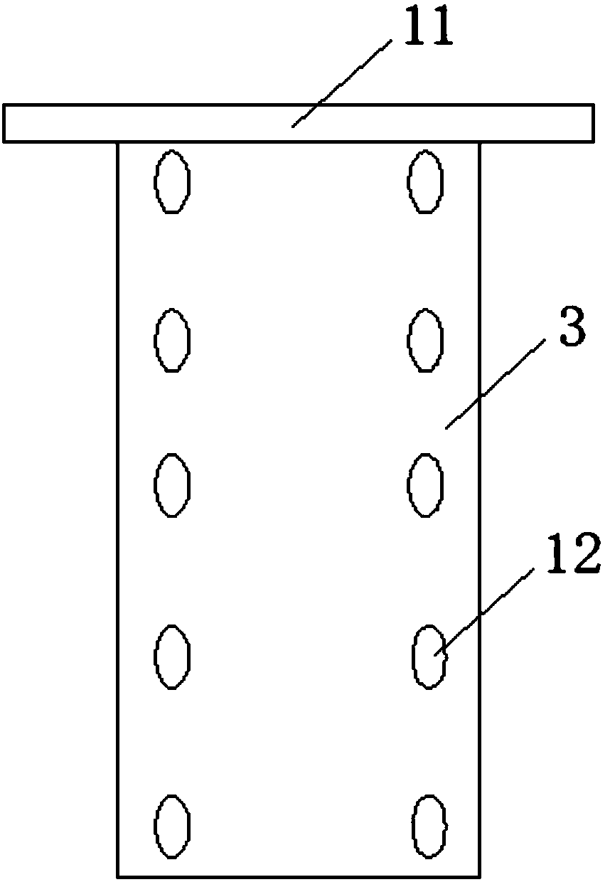
[0021] see Figure 1-5 As shown, a variable-diameter thread milling cutter includes a cutter body 1, a handle 2 and a sleeve 3. A sleeve 3 is installed below the cutter body 1, and a cutter body 1 and a handle 2 are installed above the sleeve 3. Screw blade 4 is arranged above, and retaining ring 5 is arranged in the middle of knife handle 2, mounting column 6 is arranged below retaining ring 5, and clamping blocks 7 are arranged at both ends of mounting column 6 at equal intervals, and rotating rod is arranged inside mounting column 6 8. A supporting ring 11 is arranged on the top of the sleeve 3, and the retaining ring 5 is blocked by the supporting ring 11, and several sockets 12 are arranged at equal intervals at both ends of the side wall of the sleeve 3.

Embodiment 2

[0023] In addition, please continue to Figure 1-5 As shown, the difference between it and the above-mentioned embodiment is that: the rod mounting ring 9 matching the rotating rod 8 is arranged inside the mounting column 6, and the bottom of the rotating rod 8 is provided with a transmission gear 10, which is connected to the moving coil of the motor through the transmission gear 10 , the motor drives the tool handle 2 to rotate through the transmission gear, and the screw blade 4 on the tool handle 2 is used to drill out the threads of the parts. Inside the sleeve 3 is provided a through ring 13 that matches the post 6 , and several clamping blocks 7 are matched with several insertion holes 12 . A plug 14 is provided at one end of several clamping blocks 7 , and a spring 15 is provided at one side of the plug 14 , and a welding rod 16 is provided at one side of the spring 15 . The screw blade 4 is a helical stacked structure, and one end of the handle 2 is a conical structu...


PUM


Abstract

The invention discloses a variable-diameter threaded milling cutter. The cutter comprises a cutter body, a hilt, a sleeve, a screw blade, a check ring, an installing column, clamping blocks, a rotating rod, a rod installing circle, a transmission gear, an expanding circle, inserting holes, a through circle, plugs, springs and welding rods. The variable-diameter threaded milling cutter has the beneficial effects that the two ends of the sleeve are provided with a plurality of inserting holes which are matched with the clamping blocks at equal intervals, the extension length of the hilt in the sleeve can be changed by moving the whole hilt upwards or downwards through an operation staff, so that the diameter of the whole milling cutter is changed, and the working length of the whole millingcutter is changed; after the movable adjustment is completed, then the plugs are inserted into the inserting holes with different heights, the springs on one side of the plugs are used for extruding and expanding the plugs to ensure the hilt is firmer when the hilt rotates; all components of the milling cutter are connected in a embedded and clamping mode correspondingly, all component are independent from one another to ensure assembling and connecting as well as disassembling of the milling cutter is more fast and convenient; and operation of the milling cutter is convenient, and all the components are flexibly connected.

Description

technical field [0001] The invention relates to a milling cutter, in particular to a variable-diameter thread milling cutter, which belongs to the technical field of milling cutter applications. Background technique [0002] With the rapid development of people's life, thread milling cutter is used more and more frequently in people's life. Thread milling cutter is suitable for small and medium diameter thread milling of steel, cast iron and non-ferrous metal materials, with stable cutting and high durability. Thread cutters with different coatings are used for processing different materials. [0003] The current thread milling cutter still has many deficiencies. The existing thread milling cutter has a fixed working length and cannot change the diameter. People cannot adjust the working length of the milling cutter. When the existing thread milling cutter is used for processing, Assembly installation or disassembly is not convenient and fast enough. Contents of the inven...

Claims


Application Information

Patent Timeline
Patent Type & Authority Applications(China)
IPC IPC(8): B23G5/18
CPCB23G5/18
Inventor 刘阳河王永齐
Owner 常州思智行睿精密机械有限公司
Why Eureka
Try Eureka