
Internet-based solar automatic sun tracking device

A tracking device and solar energy technology, which is applied to the control of use feedback, the support structure of photovoltaic modules, photovoltaic power generation, etc., can solve the problems of low utilization rate of solar energy, high difficulty in preparation, discomfort and popularization, etc., and achieve easy movement and stability , the effect of increasing the service life

Active Publication Date: 2018-08-24
晶科电力科技股份有限公司
View PDF6 Cites 8 Cited by
  • Summary
  • Abstract
  • Description
  • Claims
  • Application Information

AI Technical Summary

Problems solved by technology

[0002] With the exploitation of energy, there are less and less non-renewable energy on the earth. At present, scientific research around the world is focused on the utilization of renewable energy, and solar energy, as a renewable, non-polluting green new energy, has attracted people A lot of attention, the corresponding solar panels came into being, but the existing solar power generation devices are common fixed devices, the solar energy utilization rate is low, and the solar tracking system is a way to maximize the power generation of photovoltaic modules by tracking the sun in real time The device can keep the solar panel facing the sun at any time, so that the sun's rays can irradiate the solar panel vertically at any time. The power device can significantly improve the power generation efficiency of the solar photovoltaic module, while the existing solar tracking device is mainly operated manually. Regulating systems generally have problems such as complex structure, high preparation difficulty, and high cost, and are not suitable for large-scale popularization

Method used

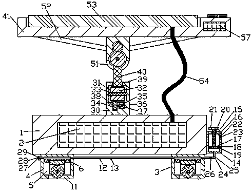

Image

  • Internet-based solar automatic sun tracking device
  • Internet-based solar automatic sun tracking device
  • Internet-based solar automatic sun tracking device

Examples


Embodiment Construction

[0015] The following will clearly and completely describe the technical solutions in the embodiments of the present invention with reference to the accompanying drawings in the embodiments of the present invention. Obviously, the described embodiments are only some, not all, embodiments of the present invention. Based on the embodiments of the present invention, all other embodiments obtained by persons of ordinary skill in the art without making creative efforts belong to the protection scope of the present invention.

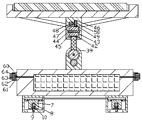
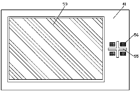
[0016] see Figure 1-4, an embodiment provided by the present invention: a solar automatic solar tracking device based on the Internet, including a fixed base plate 1, a width display device 60 is symmetrically arranged on the front and rear ends of the fixed base plate 1, and the fixed base plate 1 is internally fixed A storage battery 2 is provided, and a telescopic mobile device 3 is provided at the four corners of the lower end surface of the fixed base pl...


PUM


Abstract

The invention discloses an Internet-based solar automatic sun tracking device which comprises a fixed bottom plate. A storage battery is fixedly arranged inside the fixed bottom plate, four telescopicmoving devices are arranged at four corners of a lower end surface of the fixed bottom plate, and a right end surface of the fixed bottom plate is fixedly connected to an air inflation device. A substrate is arranged in a space above a fixed casing, a photovoltaic panel is embedded and fixedly mounted on an upper end surface of the substrate, a power transmission line is arranged at a lower end of the photovoltaic panel, and a right side of the upper end face of the substrate is provided with a cross mask. Four areas divided by the cross mask are internally and fixedly provided with four photosensitive sensors, and the right end in the substrate is provided with an integrated controller. In the work of the device, sunlight directly irradiates the photosensitive sensors and the photovoltaic panel through different angle adjustments, thereby the utilization efficiency of resources is increased, when a signal received by the integrated controller do not meet the requirements, a control device stops working, and energy is effectively saved.

Description

technical field [0001] The invention relates to the field of new energy, in particular to an Internet-based solar automatic solar tracking device. Background technique [0002] With the exploitation of energy, there are less and less non-renewable energy on the earth. At present, scientific research around the world is focused on the utilization of renewable energy, and solar energy, as a renewable, non-polluting green new energy, has attracted people A lot of attention, the corresponding solar panels came into being, but the existing solar power generation devices are common fixed devices, the solar energy utilization rate is low, and the solar tracking system is a way to maximize the power generation of photovoltaic modules by tracking the sun in real time The device can keep the solar panel facing the sun at any time, so that the sun's rays can irradiate the solar panel vertically at any time. The power device can significantly improve the power generation efficiency of t...

Claims


Application Information

Patent Timeline
Patent Type & Authority Applications(China)
IPC IPC(8): G05D3/12H02S20/32
CPCG05D3/12H02S20/32Y02E10/50
Inventor 李雄伟
Owner 晶科电力科技股份有限公司
Learn More