Power transmission line range finding method

A technology of transmission line and distance measurement method, which is applied in the direction of measuring electricity, measuring device, measuring electrical variables, etc., can solve the problem of inability of power system fault line patrol personnel to provide accurate and effective fault location information, high application cost, and single-ended fault location. The result deviates from the real fault distance, etc.

Inactive Publication Date: 2018-08-24
南京正浩电气科技有限公司
View PDF6 Cites 0 Cited by
  • Summary
  • Abstract
  • Description
  • Claims
  • Application Information

AI Technical Summary

Problems solved by technology

The traveling wave method utilizes the transmission properties of fault transient traveling waves to perform single-ended fault location. It has high precision and is not affected by the operation mode and excessive resistance. However, it requires a high sampling rate, requires a special wave recording device, and has high application costs.
The impedance method uses the voltage and current after the fault to calculate the fault loop impedance, and performs single-ended fault distance measurement according to the characteristic that the line length is proportional to the impedance. It is simple and reliable, but the distance measurement accuracy is seriously affected by the transition resistance, especially when the transition resistance is large In this case, the single-ended fault location results will seriously deviate from the real fault distance, and even exceed the total length of the transmission line, so that the single-ended fault location results lose their reference value and cannot provide accurate and effective fault location information for power system fault line inspectors. Facilitate rapid fault location finding and troubleshooting

Method used


Image

  • Power transmission line range finding method
  • Power transmission line range finding method
  • Power transmission line range finding method

Examples


Embodiment Construction

[0014] The technical solution of the present invention will be further described in detail according to the accompanying drawings.

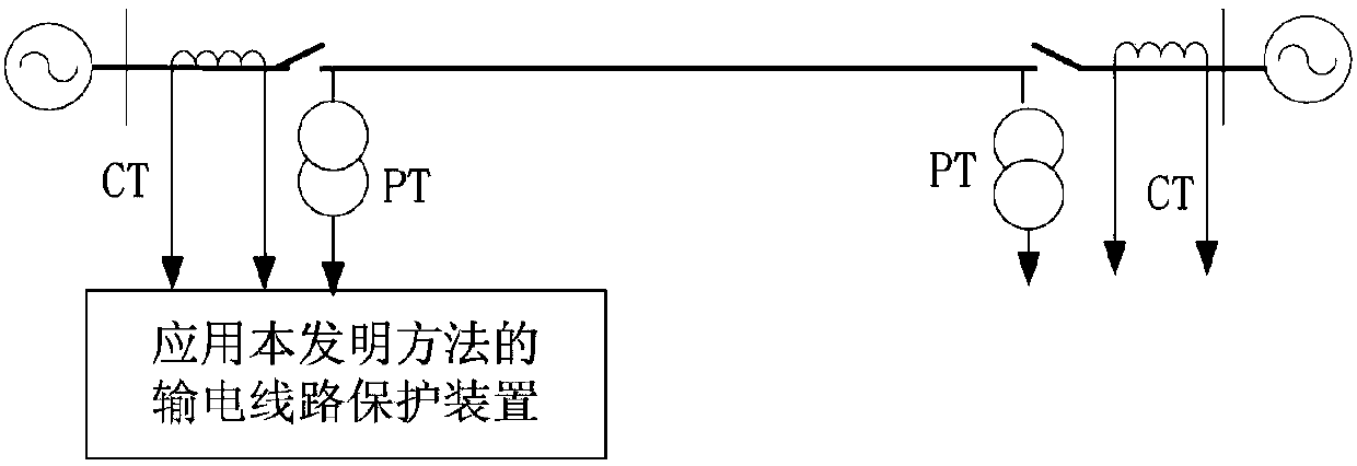
[0015] figure 1 It is a schematic diagram of the line transmission system applying the present invention. figure 1 Among them, PT is a voltage transformer, and CT is a current transformer. The data acquisition system of the protection device samples the voltage waveform of the voltage transformer PT and the current waveform of the current transformer CT at the installation place of the transmission line protection to obtain the instantaneous value of the voltage and current, and uses the instantaneous value of the voltage and current obtained by sampling Calculation of Fault Phase-to-Phase Voltage at Transmission Line Protection Installation by Liye Algorithm Fault phase current and negative sequence current between fault phases Among them, φφ=AB, BC, CA phase.

[0016] The data acquisition system of the protection device will measure the...


PUM


Abstract

The invention discloses a power transmission line range finding method. The method is characterized by calculating an equivalent resistance by using the fault phase-to-phase voltage, the fault phase-to-phase current and the fault phase-to-phase negative-sequence current of a power transmission line protection installation position; using the equivalent resistance to multiply the fault phase-to-phase negative-sequence current so as to obtain a phase-to-phase short-circuit fault point voltage; calculating the real part of the ratio of the phase-to-phase short-circuit fault point voltage and a unit-length power transmission line voltage drop and acquiring an additional fault distance due to a transition resistor; and subtracting the additional fault distance from the real part of the ratio ofthe fault phase-to-phase voltage and the unit-length power transmission line voltage drop, and acquiring a fault distance from the power transmission line protection installation position to a phase-to-phase short-circuit fault point. In the invention, the influence of the transition resistor on the single-end range finding accuracy of a phase-to-phase short-circuit fault in a power transmissionline is overcome, high range finding precision is possessed, a range finding principle is simple, a program is easy to realize, a search algorithm does not need to be used and the fault distance can be directly calculated, a range finding speed is fast and real-time performance is high.

Description

technical field [0001] The invention relates to the technical field of electric power system relay protection, in particular to a distance measuring method for a power transmission line. Background technique [0002] The single-end fault location method of transmission lines only uses the electrical quantity at one end of the transmission line for fault location, does not require communication and data synchronization equipment, has low operating costs and stable algorithms, and has been widely used in transmission lines. [0003] Single-ended fault location methods for transmission lines are mainly divided into traveling wave method and impedance method. The traveling wave method utilizes the transmission properties of fault transient traveling waves to perform single-ended fault location. It has high precision and is not affected by the operation mode and excessive resistance. However, it requires a high sampling rate, requires a special wave recording device, and has high...

Claims


Application Information

Patent Timeline
IPC IPC(8): G01R31/08
CPCG01R31/085G01R31/088
Inventor 李立浧李正佳
Owner 南京正浩电气科技有限公司
Why Eureka
Try Eureka