Traction sliding system and construction technology for erecting prefabricated crane beam in power plant

A crane beam and sliding technology, which is applied in the field of traction sliding system and construction technology, can solve the problems affecting the construction, unable to complete the erection of the crane beam on schedule, and limited lifting capacity, so as to achieve the effect of guaranteeing the lifting capacity of the equipment

Pending Publication Date: 2018-08-24
CHINA HYDROPOWER ELEVENTH ENG BUREAU ZHENGZHOU CO LTD +1
View PDF7 Cites 2 Cited by
  • Summary
  • Abstract
  • Description
  • Claims
  • Application Information

AI Technical Summary

Problems solved by technology

However, due to the geographical location of some factories, the maximum lifting capacity is limited (maximum 50t), and the beam body cannot be hoisted directly; The erection of high-altitude scaffolding will affect the normal construction in the main engine pit at the bottom, and there are certain safety risks, that is, the erection of the crane beam of the power plant cannot be completed on schedule with the existing cast-in-place and prefabricated hoisting technology

Method used


Image

  • Traction sliding system and construction technology for erecting prefabricated crane beam in power plant
  • Traction sliding system and construction technology for erecting prefabricated crane beam in power plant
  • Traction sliding system and construction technology for erecting prefabricated crane beam in power plant

Examples


Embodiment 1

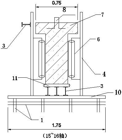
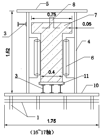
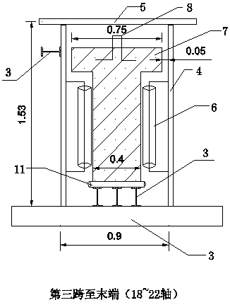
[0037] A traction-sliding system erected by a prefabricated crane beam in a power plant, such as figure 1 , 2, 3, 4, 5, and 6, the first span to the third span of the crane girder are on both sides of the platform in the installation room, and the sliding system includes the supporting sliding unit and the crane girder erected on the first span and the second span of the crane girder The sliding unit built from the third span to the end; the supporting sliding unit and the sliding unit both include a bottom foundation, a beam body placement platform 12 and a guiding and stabilizing structure arranged on the bottom foundation, and the bottom foundation supporting the sliding unit includes a supporting platform Scaffolding 1 and the operating platform scaffolding 2 separately erected on the outside of the supporting platform scaffolding, the bottom foundation of the sliding platform is the pre-embedded steel plate 15 on the clear span side of the corbel; The channel steel verti...

Embodiment 2

[0044] A construction process of a traction-sliding system for erecting prefabricated crane beams in a power plant. The traction-sliding system in the construction process is the traction-sliding system in Embodiment 1, and the system will not be described in detail here. This construction technique is used in erecting the prefabricated beams of the powerhouse of Shangmaxiangdi A Hydropower Station. The project overview is as follows:

[0045] The Shangmasangdi A Hydropower Station is located on the upper reaches of the Masangdi River in the Gandaki area of ​​western Nepal. It is a runoff water diversion hub project mainly for power generation, with a control basin area of ​​2,740km2. composed of buildings. Two mixed-flow units are installed in the factory building, with an installed capacity of 2×25MW. The main factory building has three floors; the auxiliary factory buildings are arranged on the upstream side of the main factory building and the factory area on the right si...


PUM


Abstract

The invention relates to a traction sliding system and construction technology for erecting a prefabricated crane beam in a power plant. The traction sliding system comprises a supporting sliding unitand a sliding unit, wherein the supporting sliding unit is arranged between a first span and a second span, and the sliding unit is arranged from a third span to a tail end, and the sliding unit witha single span jointly forms the siding system of the crane beam. The construction technology comprises the steps that on the basis of the siding system, the crane beam is first suspended on a beam body placing platform between the first span and the second span, and then the crane beam is slid into position by the traction sliding method. According to the aim, the invention provides the tractionsliding system and construction technology for erecting the prefabricated crane beam in the power plant in view of the prior art and the on-site actual environment and conditions, the installation andemplacement of the crane beam is completed in the condition that the crane dose not enter a main plant installation platform, the construction progress of a plant main structure is accelerated, and the work, such as erection and demolition of a high-altitude supporting platform under the cast-in-place technology of the crane beam, is avoided, and the prefabrication of the crane beam is completedahead of schedule.

Description

technical field [0001] The invention relates to the field of hydroelectric power generation, in particular to the field of erection of prefabricated beams without direct hoisting, and in particular to a traction and sliding system and construction technology for the erection of prefabricated crane beams in power plants. Background technique [0002] Concrete crane beam structures are involved in many projects, including single-span beams and continuous multi-span beams. At present, the crane girders of all power plants are generally cast-in-place and prefabricated in place, and the lifting means and work site can be guaranteed when the prefabricated beam hoisting process is adopted. However, due to the geographical location of some factories, the maximum lifting capacity is limited (maximum 50t), and the beam body cannot be hoisted directly; The high-altitude scaffolding inside will affect the normal construction in the main engine pit at the bottom, and at the same time, t...

Claims


Application Information

Patent Timeline
Patent Type & Authority Applications(China)
IPC IPC(8): E04G21/16
CPCE04G21/16
Inventor 陈雪湘曹小杰李振波辛鹏鹏庞三余
Owner CHINA HYDROPOWER ELEVENTH ENG BUREAU ZHENGZHOU CO LTD
Why Eureka
Try Eureka