Drawer adjusting device

A technology for adjusting devices and drawers, applied to drawers, household appliances, furniture parts, etc., can solve problems such as troubles, difficulties in taking items in drawers, and affecting the overall furniture texture, achieving the effect of highlighting texture and simple operation

Inactive Publication Date: 2018-08-24
苏树鹏
View PDF5 Cites 0 Cited by
  • Summary
  • Abstract
  • Description
  • Claims
  • Application Information

AI Technical Summary

Problems solved by technology

[0003] However, a drawer that cannot be fully opened will cause difficulty in picking up the items in the drawer. Therefore, in recent years, practitioners have continued to improve the slide rails and provide a slide rail that can completely expose the drawer when it is pulled out to the outermost end. , in order to fetch
[0004] Although the above-mentioned slide rails can make the use of the drawer more convenient, but the drawer will be completely exposed during use. Whether the tail (the junction of the drawer tail plate and the side panels) is smooth in appearance will directly affect the appearance of the overall furniture. Texture, but in the past because the tail of the drawer was not exposed, this problem has not been noticed, so that there are still no related components on the market that can adjust the flatness between the side panel and the tail panel, which is quite suitable for practitioners who assemble drawers. Troubled, it is necessary to improve

Method used


Image

  • Drawer adjusting device
  • Drawer adjusting device
  • Drawer adjusting device

Examples


Embodiment Construction

[0036] In order to make the above-mentioned and other objects, features and advantages of the present invention more comprehensible, the following is based on the preferred embodiments of the present invention and is described in detail as follows in conjunction with the accompanying drawings:

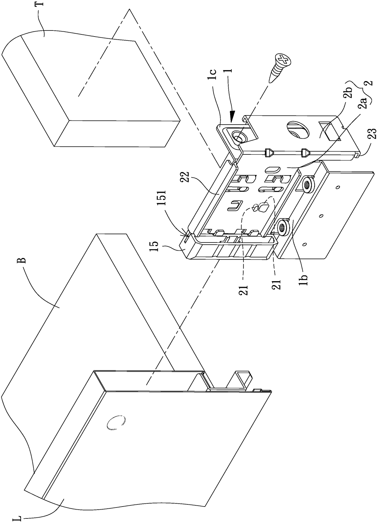
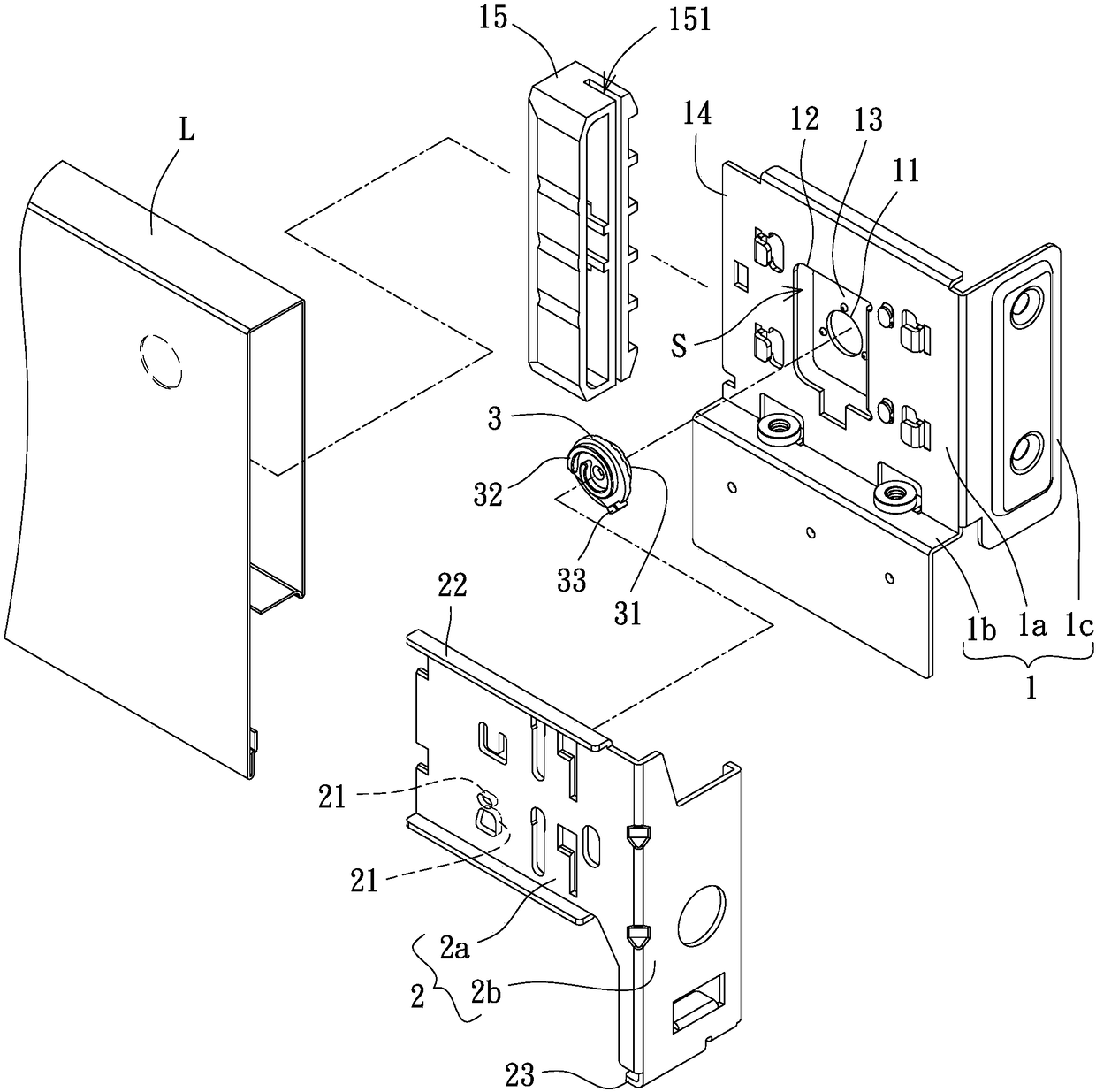
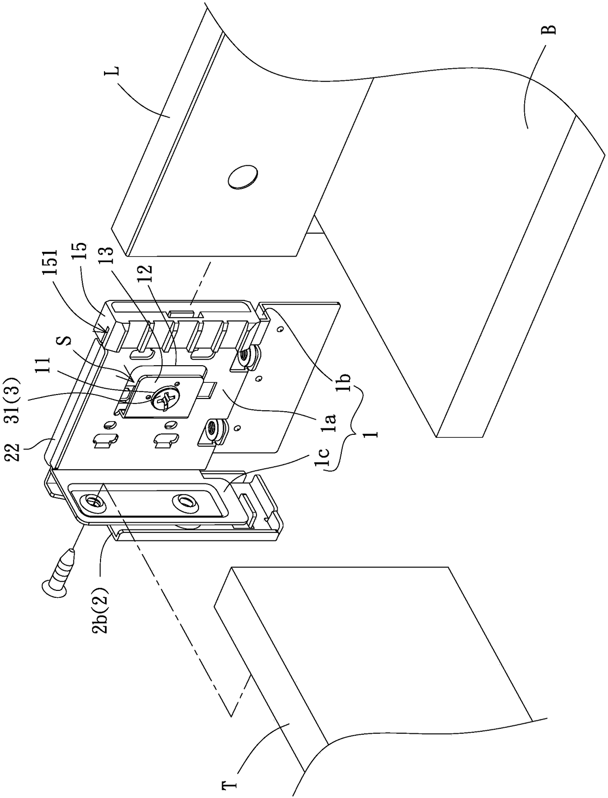
[0037] Please refer to figure 1 , figure 2 , which is an embodiment of the drawer adjustment device of the present invention. The drawer adjustment device generally includes a fixed part 1, a movable part 2 and an adjustment part 3. The fixed part 1 can be fixedly connected to the tail plate T of the drawer and Bottom plate B, a part of the fixed part 1 and the movable part 2 penetrates into the side plate L of the drawer, and the adjusting part 3 is arranged between the fixed part 1 and the movable part 2; by rotating the adjusting part 3 , causing the movable part 2 to move relative to the fixed part 1, thereby driving the side plate L to rise or fall.

[0038] Specifically, the f...


PUM


Abstract

Provided is a drawer adjusting device that is used for resolving the problem that a conventional drawer fails to adjust the degree of flatness between a side board and a tail board. The drawer adjusting device comprises a fixed-connecting part, a movable part and an adjusting part. The fixed-connecting part is equipped with an adjusting hole. The movable part is provided with at least two limitingblocks. An upper pushing part is arranged at the top end of the movable part. A lower pushing part is arranged at the bottom end of the movable part. A control part is formed on one side of the adjusting part and a spiral projection is arranged on the other side thereof. The adjusting part is arranged between the fixedly-connected part and the movable part. The control part is aligned at the adjusting hole. The spiral projection penetrates and stretches through a gap between at least two limiting blocks.

Description

technical field [0001] The invention relates to a part for a drawer, in particular to a drawer adjustment device assembled at the tail end of the drawer to adjust the flatness between the side plate and the end plate of the drawer. Background technique [0002] The early furniture drawers did not have slide rails. In addition to being difficult to open and close the drawers, the drawers would fall when pulled too far; later, the slide rails were installed to make the drawer open and close more smoothly, and the slide rails can pull the drawer open The extent forms a limit, which effectively prevents the drawer from falling and improves the safety of use. [0003] However, a drawer that cannot be fully opened will cause difficulty in picking up the items in the drawer. Therefore, in recent years, practitioners have continued to improve the slide rails and provide a slide rail that can completely expose the drawer when it is pulled out to the outermost end. , to fetch objects...

Claims


Application Information

Patent Timeline
Patent Type & Authority Applications(China)
IPC IPC(8): A47B88/407A47B88/90A47B88/944
CPCA47B2210/092A47B95/00A47B88/90A47B2088/902A47B88/956A47B88/919A47B88/941A47B2088/94
Inventor 苏树鹏
Owner 苏树鹏
Why Eureka
Try Eureka