
Rubber tapping equipment with double-knife-edge structure

A double-edged, rubber-tapping technology, applied in forestry, application, agriculture, etc., can solve the problems of not being able to be cut, affecting the service life of rubber trees, and large labor investment, etc., to achieve the effect of good lifting movement

Pending Publication Date: 2018-08-24
AGRI MACHINERY INST CHINESE TROPICAL ACAD OF SCI
View PDF6 Cites 6 Cited by
  • Summary
  • Abstract
  • Description
  • Claims
  • Application Information

AI Technical Summary

Problems solved by technology

[0002] Since human beings discovered that natural rubber can be collected from rubber trees, the method of making rubber bark to form rubber slides has always been cutting with a hand-held rubber-tapping knife; although electric rubber-tapping knives have appeared in modern times, manual hand-held operation is still required
The quality of rubber tapping technology will not only affect the output of rubber tapping, but also affect the output of the entire production cycle, and even affect the service life of rubber trees
Manual tapping of rubber makes rubber production a lot of labor input, which has become the bottleneck of rubber production
At the same time, the rubber tapping knife installed on the existing rubber tapping equipment, when tapping the rubber tree, the rubber tree surface under the rubber tapping knife cannot be cut because the rubber tapping knife has a certain width. Sex completes efficient cutting of rubber tree

Method used


Image

  • Rubber tapping equipment with double-knife-edge structure
  • Rubber tapping equipment with double-knife-edge structure
  • Rubber tapping equipment with double-knife-edge structure

Examples


Embodiment Construction

[0025] The accompanying drawings are for illustrative purposes only, and should not be construed as limitations on this patent; in order to better illustrate this embodiment, certain components in the accompanying drawings will be omitted, enlarged or reduced, and do not represent the size of the actual product; for those skilled in the art It is understandable that some well-known structures and descriptions thereof may be omitted in the drawings. The positional relationship described in the drawings is for illustrative purposes only, and should not be construed as a limitation on this patent.

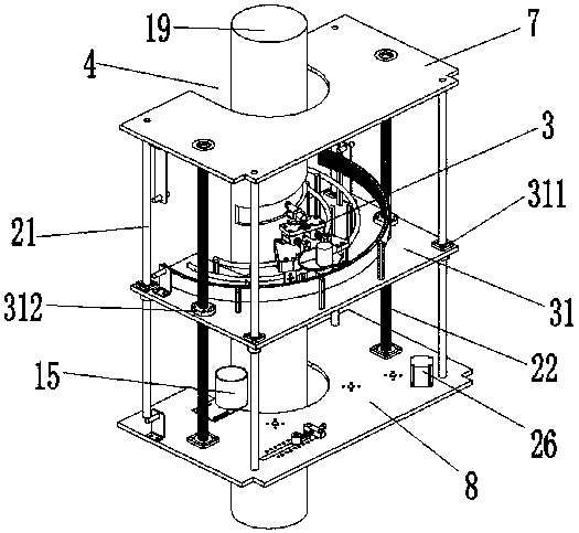
[0026] Such as Figure 1 to Figure 3 Shown, a kind of tapping equipment with double-blade structure, wherein, comprise outer frame 1, be arranged on the vertical lifting feeding device 2 on described outer frame 1 and be arranged on described vertical lifting feeding device 2 and can move along The vertical lift feeding device 2 is a spiral rubber tapping device 3 that lifts vertical...


PUM


Abstract

The invention provides rubber tapping equipment with a double-knife-edge structure. The equipment comprises an outer frame, a vertical lifting work feeder arranged on the outer frame and a spiral rubber-tapping device arranged on the vertical lifting work feeder and capable of vertical lifting along the vertical lifting work feeder; and the spiral rubber-tapping device is provided with a rubber-tapping knife with an adjustable extending distance and a double-sided knife edge, the outer frame is provided with a tree trunk fixing position used for accommodating a tree trunk of a rubber tree, theposition, corresponding to the tree trunk fixing position, of one side of the outer frame is provided with a detachable movable baffle, the top end of the outer frame is provided with a solar panel and a control system, the vertical lifting work feeder and the spiral rubber-tapping device are connected with the solar panel and the control system, and the part, located at the edge position of thetree trunk fixing position, of the bottom of the outer frame is provided with a rubber collecting barrel. The equipment provided by the invention can replace manual rubber tapping, not only improves rubber tapping efficiency, but also improves rubber tapping quality; and the equipment is provided with the rubber tapping knife with a front knife edge and back knife blade structure, so that the equipment facilitates effective and high-efficiency cutting of the rubber tree.

Description

technical field [0001] The invention relates to the technical field of agricultural automation machinery, and more specifically, relates to a rubber tapping device with a double-blade structure. Background technique [0002] Since humans discovered that natural rubber can be collected from rubber trees, the method of making rubber bark to form rubber slides has always been cutting with a manual hand-held rubber tapping knife; although electric rubber tapping knives have appeared in modern times, manual hand-held operation is still required. The quality of rubber tapping technology will not only affect the output of rubber tapping, but also the output of the whole production cycle, and even affect the service life of rubber trees. Manual tapping of rubber makes rubber production a lot of labor input, which has become the bottleneck of rubber production. At the same time, the rubber tapping knife installed on the existing rubber tapping equipment, when tapping the rubber tree...

Claims


Application Information

Patent Timeline
Patent Type & Authority Applications(China)
IPC IPC(8): A01G23/12A01G23/10
CPCA01G23/10A01G23/12Y02P60/12
Inventor 张园邓怡国王业勤韦丽娇李明董学虎
Owner AGRI MACHINERY INST CHINESE TROPICAL ACAD OF SCI
Learn More