
A battery box suitable for microgravity environment

A battery box and microgravity technology, which is applied to battery pack components, circuits, electrical components, etc., can solve problems such as the clamp is not tight, the hook is easy to break, and the battery box is not suitable for the microgravity environment.

Active Publication Date: 2021-02-02
HUBEI SANJIANG AEROSPACE HONGFENG CONTROL
View PDF9 Cites 0 Cited by
  • Summary
  • Abstract
  • Description
  • Claims
  • Application Information

AI Technical Summary

Problems solved by technology

The battery box with this structure is not suitable for the microgravity environment. In the microgravity environment, objects are prone to float and collide. The control of the buckle will be fully opened, so that the unprotected battery of the box is prone to drift or be ejected by the spring to affect the use of electrical appliances
In addition, this kind of snap-on battery box cannot be made of hard materials, otherwise the buckle will be difficult to snap in. At the same time, the hook of this locking mechanism is easy to break or deform during use, resulting in the failure of the locking mechanism or the buckle is not tight. , so that the opening and closing of the shell and the cover is very inconvenient

Method used


Image

  • A battery box suitable for microgravity environment
  • A battery box suitable for microgravity environment
  • A battery box suitable for microgravity environment

Examples


Embodiment Construction

[0027] In order to make the object, technical solution and advantages of the present invention clearer, the present invention will be further described in detail below in conjunction with the accompanying drawings and embodiments. It should be understood that the specific embodiments described here are only used to explain the present invention, not to limit the present invention.

[0028] In addition, the technical features involved in the various embodiments of the present invention described below can be combined with each other as long as they do not constitute a conflict with each other. The present invention will be further described in detail below in combination with specific embodiments.

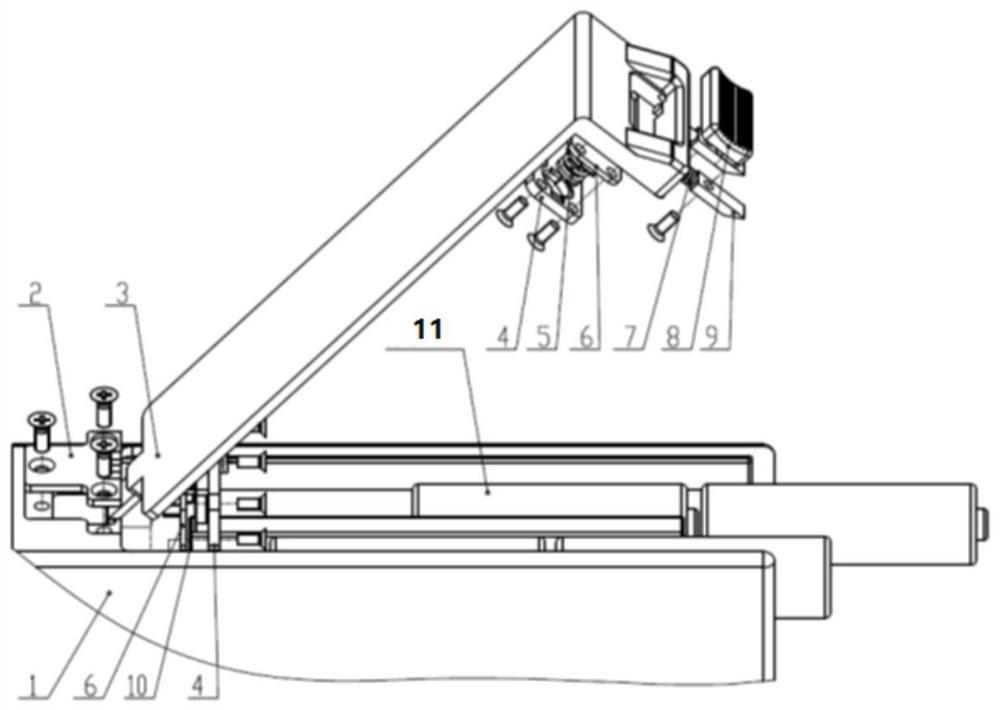
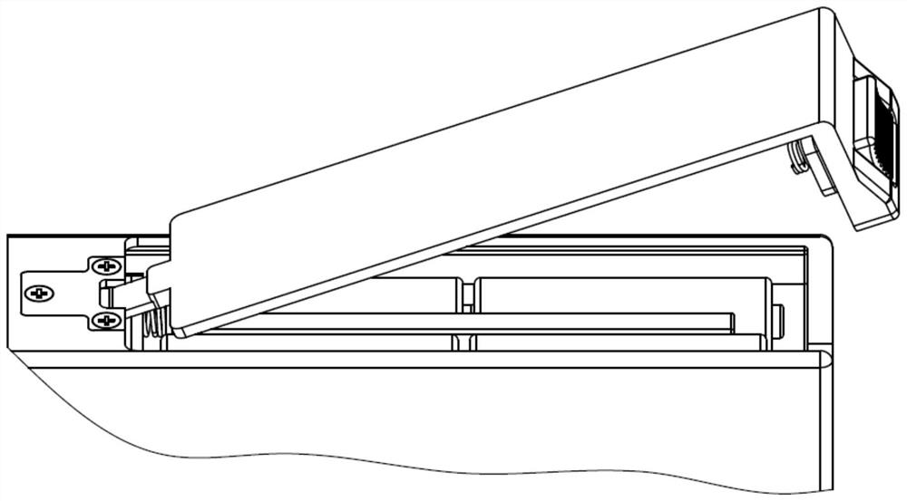
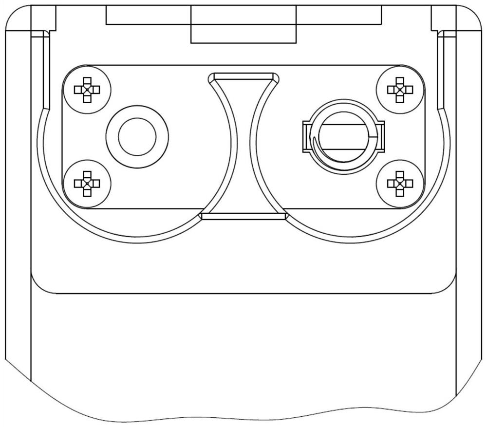
[0029] figure 1 It is a schematic structural diagram of a battery box according to an embodiment of the present invention. Such as figure 1 As shown, the battery box of this embodiment includes a box body 1, a hinge cover plate 2, a box cover 3, an electrode pressure plate 4, a c...


PUM


Abstract

The invention discloses a battery box suitable for a microgravity environment, which comprises a box body and a box cover. The box body includes a body with a groove at one end, and an opening groove at the other end, and is sealed by a hinge cover plate with a hole. And the bottom of the opening groove is provided with a pin groove, the box cover is arranged on the box body, and one end is provided with a connecting part, through which the connecting part is hinged with the box body, and the other end is provided with a vertically protruding baffle plate, the box cover Driven to move in its length direction can drive the pin shaft to reciprocate in the pin shaft groove, so that the second connecting part is constrained by the hinge cover plate and pressed against the box body and locked by the locking and unlocking parts, Or the second connecting part is free from the constraints of the hinge cover so that the connecting part can rotate around the pin shaft to realize the opening of the box cover. The optimized design of the connection between the hinge and the lid of the battery box of the present invention can prevent misoperation in the microgravity environment from causing the batteries in the battery box to drift, and realize fast locking to facilitate battery replacement operations in the microgravity environment.

Description

technical field [0001] The invention belongs to the technical field of battery boxes, and in particular relates to a battery box suitable for a microgravity environment. Background technique [0002] With the development of manned spaceflight technology and the construction of aerospace space stations, some low-voltage DC electrical equipment needs to be equipped on space stations or manned aircraft. Therefore, battery boxes suitable for use in microgravity environments are required. [0003] A conventional battery box usually includes a box body, a cover body, and a hollow cavity formed by the combination of the box body and the cover body, which can accommodate the battery. Conductors for electrical connection between the battery and the battery terminals of the electrical appliance are arranged in the hollow cavity. For example, Chinese patent document 201420581591.1 discloses a battery box, wherein a locking mechanism of a hook and a buckle is used between the shell and ...

Claims


Application Information

Patent Timeline
Patent Type & Authority Patents(China)
IPC IPC(8): H01M50/244H01M50/291H01M50/20
CPCH01M50/20Y02E60/10
Inventor 段友明樊贺斌刘成强宋超凡渠向东王浩洲陈竹宁李畅
Owner HUBEI SANJIANG AEROSPACE HONGFENG CONTROL
Learn More