
Continuous push type scalp clamping device

A scalp clip and push-type technology, applied in the field of medical devices, can solve the problems of increased pain for patients, prolonged operation time, and long operation time, and achieve the effects of convenient and quick operation, shortened operation time, and improved operation efficiency

Pending Publication Date: 2018-08-21
元毓医疗科技(上海)有限公司
View PDF0 Cites 4 Cited by
  • Summary
  • Abstract
  • Description
  • Claims
  • Application Information

AI Technical Summary

Problems solved by technology

[0003] The existing scalp clamping equipment cannot continuously clamp the scalp. During the operation, the doctor must first install the scalp clamp on the scalp clamping equipment by hand, and pull the two scalps at the incision with one hand. , use the other hand to clamp the scalp section of the scalp, each clip needs to be reinstalled, the operation is very troublesome, and the operation time is long and the efficiency is not high
Due to the long operation time of clamping the scalp, the operation time is prolonged, which leads to an increase in the use of anesthetics during the operation, and an increase in the amount of bleeding from the scalp, which increases the pain of the patient.
[0004] In addition, the existing scalp clamping instruments are usually made of two materials, stainless steel and plastic, and the cost of stainless steel is high, and it is difficult to manufacture and process

Method used


Image

  • Continuous push type scalp clamping device
  • Continuous push type scalp clamping device
  • Continuous push type scalp clamping device

Examples


Embodiment

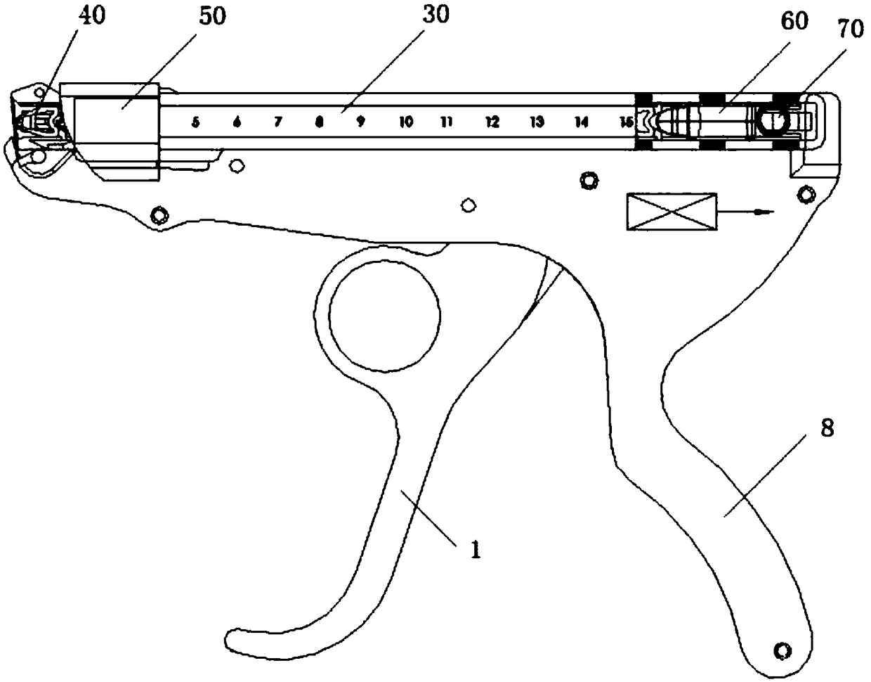
[0062] The invention relates to a continuously advancing scalp clamping instrument, which comprises a scalp clamp (applying forceps) and a scalp clamp box.

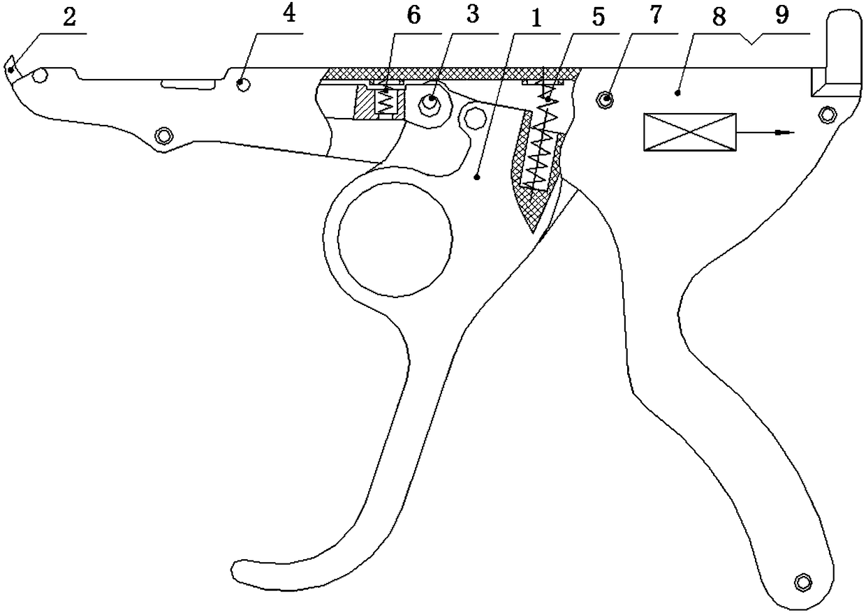
[0063] like figure 1 As shown, the scalp tongs (release pliers) in the present invention are gun-type scalp tongs, including firing handle 1, control lever 2, elastic cylindrical pin 3, positioning nail 4, large spring 5, small spring 6, hexagon socket head cap screw 7, the left half gun shell 8, the right half gun shell 9, are assembled by above-mentioned each parts. Left half gun shell 8, right half gun shell 9 are combined into the gun shell of gun type scalp clamp. Control lever 2, percussion handle 1 top, big spring 5, little spring 6 are arranged in the gun shell that is combined by left half gun shell 8, right half gun shell 9. The middle part of the control rod 2 is fixedly connected with the front part of the left half gun shell 8 top and the right half gun shell 9 top by the positioning nail 4. The upper part...


PUM


Abstract

The invention discloses a continuous push type scalp clamping device which includes a scalp clamp and a scalp clamping box. The scalp clamp includes a percussion handle, a control lever, an elastic cylindrical pin, a positioning pin, a screw, a large spring, a small spring, a left half gun casing and a right half gun casing. The scalp clamping box includes a clip, scalp clips, a clip locking button, a conveying block and a coil spring. The scalp clamping box is mounted on the scalp clamp, the percussion handle is triggered, the head of the control lever abuts against the lower rear portion ofthe scalp clip to make the scalp clip automatically opened, the opened scalp clip is placed on the scalp, the percussion handle is loosened, and the scalp clip automatically clamps the scalp; and by continuous triggering and loosening of the percussion handle, the plurality of scalp clips can be released continuously to clamp the scalp. The device is convenient to operate and use and can automatically shortens the scalp clamping operation time and greatly improve operation efficiency; at the same time, the amount of bleeding of scalp during the scalp clamping operation can be greatly reduced,the operation time can be reduced by 2 / 3, and the amount of anesthetic used during an operation can also be reduced.

Description

technical field [0001] The invention belongs to the technical field of medical devices, and relates to a continuously advancing scalp clamping device. Background technique [0002] Scalp clips are mainly used for clamping the scalp during brain surgery for hemostasis and fixation. During the operation, the doctor needs to clamp the scalp clip by matching pliers (i.e. scalp clips), and the scalp is clamped by the scalp clip to perform the operation. [0003] The existing scalp clamping equipment cannot continuously clamp the scalp. During the operation, the doctor must first install the scalp clamp on the scalp clamping equipment by hand, and pull the two scalps at the incision with one hand. , the other hand clamps a section of scalp with the scalp clip, and each scalp clip needs to be reinstalled once, which is very troublesome to use, and the operation time is long and the efficiency is not high. Due to the long operation time of clamping the scalp, the operation time is...

Claims


Application Information

Patent Timeline
Patent Type & Authority Applications(China)
IPC IPC(8): A61B17/128A61B17/122
CPCA61B17/1222A61B17/1285A61B2017/12004
Inventor 高修金
Owner 元毓医疗科技(上海)有限公司
Learn More