Power electrical cabinet with vibration damping moving seat

A technology for moving seats and electrical cabinets, which is applied in the direction of electrical components, substation/power distribution device casings, and anti-seismic equipment, etc., which can solve the problems of limited shock absorption effect, difficulty in achieving the effect, and affecting the scope of application, etc., so as to achieve good practicability and reduce Damage, effects that increase range of use

Inactive Publication Date: 2018-08-17
王恒标
View PDF0 Cites 0 Cited by
  • Summary
  • Abstract
  • Description
  • Claims
  • Application Information

AI Technical Summary

Problems solved by technology

[0002] The electrical cabinet is a cabinet made of steel to protect the normal operation of the components. Since the power and electrical cabinets need to be installed on site, there will be certain vibrations during the handling or installation process, and because the electrical cabinets are placed. Components and components are easily damaged after vibration. The electric cabinets of the prior art mostly use gaskets for shock absorption, and the shock absorption effect is very limited, and it is difficult to achieve the desired effect. One position cannot be moved, which will also affect its scope of application to a certain extent, and its practicability is limited

Method used


Image

  • Power electrical cabinet with vibration damping moving seat
  • Power electrical cabinet with vibration damping moving seat

Examples


Embodiment 1

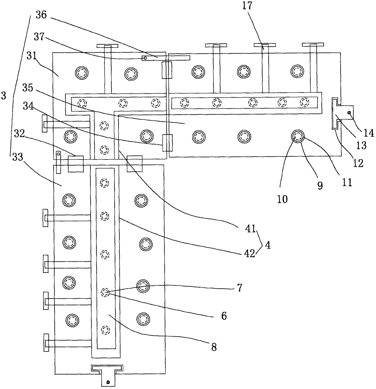
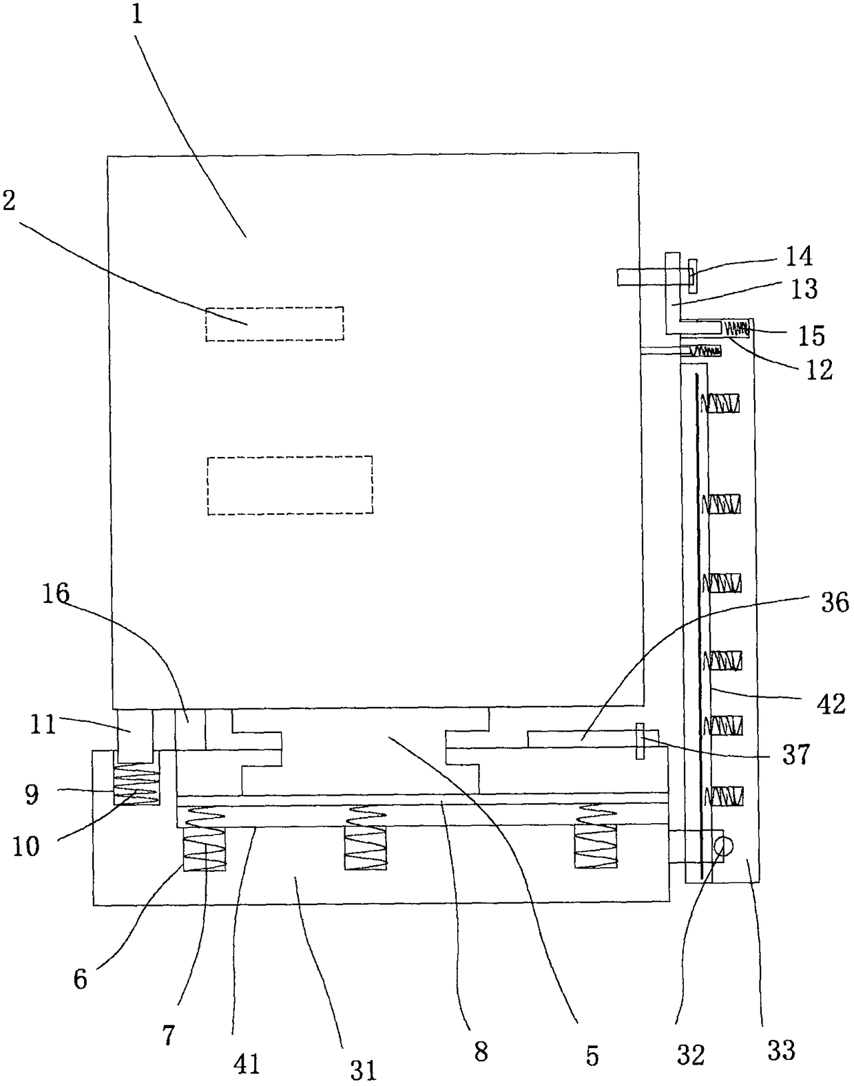
[0015] figure 1 and figure 2 A specific embodiment of the invention is shown in which figure 1 It is a structural schematic diagram of a shock-absorbing mobile seat in the present invention; figure 2 It is an overall structure diagram of the present invention.

[0016] See figure 1 and figure 2 , a power electrical cabinet with a shock-absorbing mobile seat, including a cabinet body 1, a bracket 2 is arranged in the cabinet body 1, components are fixed on the bracket 2, and a shock-absorbing mobile seat 3 is also provided. The shock-absorbing mobile seat 3 is provided with a mobile guide groove 4, and the bottom wall of the cabinet body 1 is fixed with an I-shaped mobile slider 5 matched with the mobile guide groove 4. On the shock-absorbing mobile seat 3 A round hole 6 is evenly fixed on the bottom wall of the moving guide groove, a spring 7 is fixed in the hole 6, a bearing plate 8 is arranged on the bottom wall of the moving guide groove 4, and the bottom surface of...


PUM


Abstract

The invention discloses a power electrical cabinet with a vibration damping moving seat. The power electrical cabinet comprises a cabinet body which is internally provided with a bracket. The power electrical cabinet is also provided with the vibration damping moving seat. The vibration damping moving seat is provided with a moving guiding trough. An H-shaped moving slide block which matches the moving guiding trough is fixed on the bottom wall of the cabinet body. Circular holes are uniformly fixed on the bottom wall of the moving guiding trough of the vibration damping moving seat. A springis fixed in each circular hole. The bottom wall of the moving guiding trough is provided with a bearing pressure plate. Vibration damping recessed chambers are uniformly fixed to the top surface of the vibration damping moving seat. A vibration damping abutting spring is arranged in the vibration damping recessed chamber. A rubber protecting abutting column is fixed to top of the vibration dampingabutting spring. The power electrical cabinet has advantages of reasonable structure and convenient operation. The power electrical cabinet has advantages of reducing damage of the cabinet in a transportation process caused by vibration, facilitating moving and position adjustment of the cabinet body, expanding use range, realizing high stability in use, and obtaining high applicability and highpracticability.

Description

technical field [0001] The invention belongs to the technical field of electric power cabinets, and in particular relates to a power electric cabinet with a shock-absorbing moving seat. Background technique [0002] The electrical cabinet is a cabinet made of steel to protect the normal operation of the components. Since the power and electrical cabinets need to be installed on site, there will be certain vibrations during the handling or installation process, and because the electrical cabinets are placed. Components and components are easily damaged after vibration. The electric cabinets of the prior art mostly use gaskets for shock absorption, and the shock absorption effect is very limited, and it is difficult to achieve the desired effect. One position cannot be moved, thereby also affecting its scope of application to a certain extent, and its practicability is limited. Contents of the invention [0003] The object of the present invention is to provide a power cabi...

Claims


Application Information

Patent Timeline
Patent Type & Authority Applications(China)
IPC IPC(8): H02B1/30H02B1/54H02B1/52
CPCH02B1/30H02B1/303H02B1/52H02B1/54
Inventor 王恒标
Owner 王恒标
Why Eureka
Try Eureka