
Floating type pipeline diagnostic device

A diagnostic device and floating technology, which is applied in the pipeline system, TV, color TV components and other directions, can solve the problems of easy damage to the pipeline, complicated equipment operation, difficult and small diameter pipeline, etc., to reduce the workload and reduce the cost. , the effect of low overall density

Pending Publication Date: 2018-08-17
SHENZHEN GRADUATE SCHOOL TSINGHUA UNIV
View PDF17 Cites 2 Cited by
  • Summary
  • Abstract
  • Description
  • Claims
  • Application Information

AI Technical Summary

Problems solved by technology

The disadvantages of the above two types of equipment are that their structures are complex, so the cost is high and the volume is large, and it is difficult to use them in small-diameter pipelines. At the same time, the operation of these two types of equipment is also relatively complicated, and they are prone to damage in pipelines with unknown conditions.

Method used


Image

  • Floating type pipeline diagnostic device

Examples


example

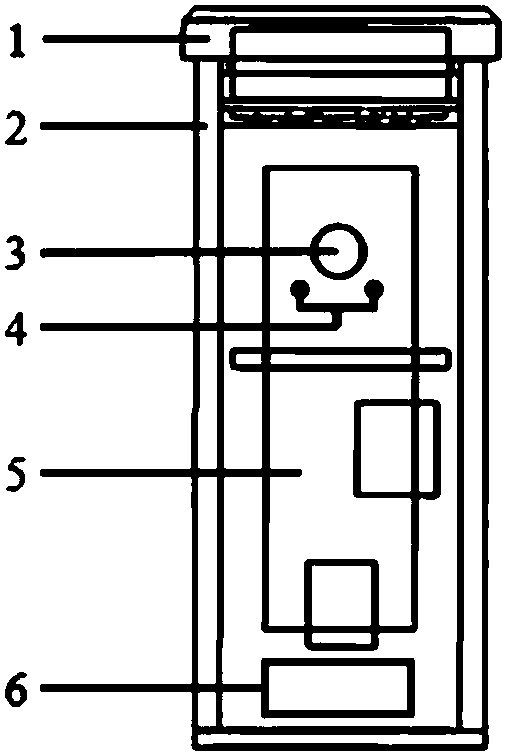
[0047] A floating pipeline diagnostic device, which uses strong and rigid plastic material as the shell, and is designed as a cylinder. The device includes a camera, LED lighting components, data storage components and rechargeable batteries. These four parts are fixed inside the cylinder and passed through The sealing cover composed of the cover and the rubber sealing ring forms a closed space inside the device and isolates it from water. Its overall density is lower than that of water, and it floats on the water surface after entering the pipeline. LED lights are distributed on both sides of the camera to illuminate the field of view of the camera. The camera can take pictures of the internal conditions of the pipeline and store them in the memory. The design size (diameter of the bottom surface of the cylinder × length of the cylinder) of the floating pipeline diagnostic device applicable to the pipe diameter above 100mm is 40×90mm.

[0048] The above solutions provide drai...


PUM


Abstract

The invention discloses a floating type pipeline diagnostic device. The floating type pipeline diagnostic device comprises a tubular shell as well as a camera, an illuminating part, a data storage part and a battery which are arranged in the tubular shell in a sealing mode, wherein integral density of the diagnostic device is smaller than that of water, so that the diagnostic device can be floatedon water; the battery is connected with the camera, the illuminating part and the data storage part, and provides electric energy; the camera is connected with the data storage part; the tubular shell is provided with a transparent part; the camera takes an outside condition of the tubular shell through the transparent part, and stores the taken content to the data storage part; and the illuminating part is used for illuminating view of the camera. The floating type pipeline diagnostic device can conveniently and quickly explore a condition inside a pipeline in a key catchment area, and reduces cost.

Description

technical field [0001] The invention relates to a floating pipeline diagnosis device. Background technique [0002] With the continuous construction of the city, the rain and sewage drainage pipe network system is also continuously expanded and improved. However, while the combined drainage system is mostly used in the old urban area, the divergent drainage system is used in many new urban areas, resulting in different drainage systems in the city. The pipeline network is staggered, the pipeline conditions are complicated, and problems such as rain and sewage mixed connection and leakage caused by aging and damaged pipeline network have occurred. The emergence of these problems has brought a lot of inconvenience to the drainage pipe network management department in diagnosing the pipe network structure and internal physical conditions, and also brought difficulties to the collection of urban rainwater and sewage, thus affecting the quality of urban water environment. [000...

Claims


Application Information

Patent Timeline
Patent Type & Authority Applications(China)
IPC IPC(8): F17D5/06F17D3/01H04N5/225H04N5/235H04N5/76
CPCH04N5/76F17D3/01F17D5/06H04N23/51H04N23/50H04N23/74
Inventor 管运涛戈鑫朱光宇
Owner SHENZHEN GRADUATE SCHOOL TSINGHUA UNIV
Learn More