Wastewater treatment or deep-water mixing aerating apparatus

A sewage treatment, deep water technology, applied in water/sludge/sewage treatment, sustainable biological treatment, water aeration, etc., can solve the problems of many pool bottoms, complex structure, large investment, etc. The effect of high oxygen efficiency and high oxygen utilization rate

Pending Publication Date: 2018-08-17
新乡市蓝海环境科技有限公司
View PDF1 Cites 0 Cited by
  • Summary
  • Abstract
  • Description
  • Claims
  • Application Information

AI Technical Summary

Problems solved by technology

[0002] At present, the sewage biochemical oxygenation system mostly adopts traditional microporous oxygenation and mechanical surface oxygenation. The traditional microporous oxygenation system has better oxygenation effect, but has disadvantages such as inconvenient maintenance, large investment and large floor area, and the pool There will be more dead mud deposits at the bottom; the dissolved oxygen on the surface of the machine relies on the rotation of the wheel on the water surface to generate negative pressure and inhale air to achieve the purpose of oxygenation, but there are still complex structures, inconvenient maintenance, large investment, and serious noise. and other problems, there will be more dead mud deposits at the bottom of the pool
[0003] Patent No. 201510289868.2 authorized by the National Patent Office, titled "A deep-water lake reservoir composite flow-making aeration device" uses the flow-making device to fill the water body at the bottom of the reservoir with air, and uses the aeration device to remove water-insoluble substances from the air. The gas and part of the dissolved oxygen enter the aeration device through the gas diversion device, and the water layer is mixed, but it cannot dive to the bottom of the pool to operate, and it cannot fully mix the water body efficiently to achieve the purpose of oxygenation, so that the bottom of the pool will not be regenerated. There is dead mud

Method used


Image

  • Wastewater treatment or deep-water mixing aerating apparatus
  • Wastewater treatment or deep-water mixing aerating apparatus
  • Wastewater treatment or deep-water mixing aerating apparatus

Examples


Embodiment Construction

[0009] Embodiments of the present invention are described in detail below, examples of which are shown in the drawings, wherein the same or similar reference numerals designate the same or similar elements or elements having the same or similar functions throughout. The embodiments described below by referring to the figures are exemplary and are intended to explain the present invention and should not be construed as limiting the present invention.

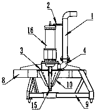
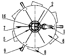
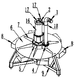
[0010] Specific examples figure 1 and image 3 As shown, the sewage treatment or deep water mixed oxygenation device of the present invention comprises an air inlet pipe 1, an air inlet pipe fixing device 2, a support 3, a tripod support 9, an impeller 10, a locking rod 15 and a reduction motor 16. The bracket is connected to the machine base through the disc, and the geared motor 15 is connected to the machine base through the geared motor mounting base 5. The jet barrels 8 are evenly distributed on the machine base, and the ma...


PUM


Abstract

The invention discloses a wastewater treatment or deep-water mixing aerating apparatus. A tripod is connected with a base through a disc; a reduction motor is connected with the base via a reduction motor mounting block; jet barrels are distributed evenly on the base; an intake port abutted to an intake tube is reserved in the base; an output shaft of the reduction motor is fitted with a blade wheel and locked via a locking bar. An intake tube fixture allows the intake tube to be fixed via a U-shaped tube clamp; the intake tube fixture is arranged on the reduction motor; the length of the intake tube is determined according to water depth. Underwater air supply is employed herein; air contacts water for long time; oxygen dissolving efficiency is high; the blade wheel structure helps fullymix the air and water, so that oxygen utilization rate is high; the apparatus is placed on a tank bed, runs stably and is convenient to maintain and free of noise; the apparatus runs at the tank bed,so that aerating is achieved, and the tank bed never experiences stagnant mud.

Description

technical field [0001] The invention relates to a mixed oxygenation device, which is especially suitable for sewage treatment or deep water mixed oxygenation. Background technique [0002] At present, the sewage biochemical oxygenation system mostly adopts traditional microporous oxygenation and mechanical surface oxygenation. The traditional microporous oxygenation system has better oxygenation effect, but has disadvantages such as inconvenient maintenance, large investment, and large floor area. There will be more dead mud deposits at the bottom; the dissolved oxygen on the surface of the machine relies on the rotation of the wheel on the water surface to generate negative pressure and inhale air to achieve the purpose of oxygenation, but there are still complex structures, inconvenient maintenance, large investment, and serious noise. And other problems, there will be more dead mud deposits at the bottom of the pool. [0003] Patent No. 201510289868.2 authorized by the N...

Claims


Application Information

Patent Timeline
IPC IPC(8): C02F7/00
CPCC02F7/00Y02W10/10
Inventor 任国龙李保军邢孟磊周志娟潘建文潘健康安正燕彭龙王壮王历凯张庆哲
Owner 新乡市蓝海环境科技有限公司
Why Eureka
Try Eureka