
Airplane wing body docking assembling device, method and system

A wing body and aircraft technology, applied in the field of aircraft intelligent assembly, can solve the problems of position and attitude adjustment of unconnected parts, unsatisfactory wing body butting quality, easy deformation, etc.

Active Publication Date: 2018-08-17
NANCHANG HANGKONG UNIVERSITY
View PDF14 Cites 25 Cited by
  • Summary
  • Abstract
  • Description
  • Claims
  • Application Information

AI Technical Summary

Problems solved by technology

Due to the easy deformation of the docking surfaces of aircraft components, there are multiple error sources such as part manufacturing and part assembly coupling. Even if the position accuracy of the attitude adjustment reference point meets the docking assembly requirements, the mating surfaces may not meet the docking accuracy requirements.
In addition, the opening of the wing-body mating surface is poor, and the accuracy of the traditional mating part is carried out by naked eye observation. Poor sex causes observers to be in poor working conditions for a long time
Moreover, due to the complex structure and poor openness of the aircraft's mating parts, it is impossible to accurately judge the docking state of the fork lugs and feed back their relative pose errors only by naked eyes.
Therefore, the current method of using a laser tracker to measure the attitude control points arranged on the docking assembly parts is an open-loop control method, which does not realize the pose feedback based on the quality of the mating surfaces of the assembly parts, and cannot perform docking parts based on the actual mating accuracy of the mating surfaces. The pose adjustment of the existing aircraft wing-body joint assembly process is inefficient, and the joint quality of the wing-body body cannot meet the high-precision requirements.

Method used


Image

  • Airplane wing body docking assembling device, method and system
  • Airplane wing body docking assembling device, method and system
  • Airplane wing body docking assembling device, method and system

Examples


Embodiment Construction

[0077] The following will clearly and completely describe the technical solutions in the embodiments of the present invention with reference to the accompanying drawings in the embodiments of the present invention. Obviously, the described embodiments are only some, not all, embodiments of the present invention. Based on the embodiments of the present invention, all other embodiments obtained by persons of ordinary skill in the art without making creative efforts belong to the protection scope of the present invention.

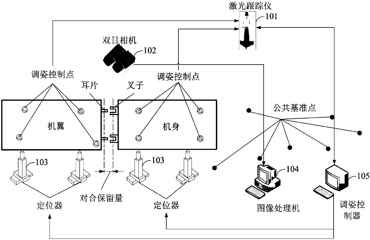
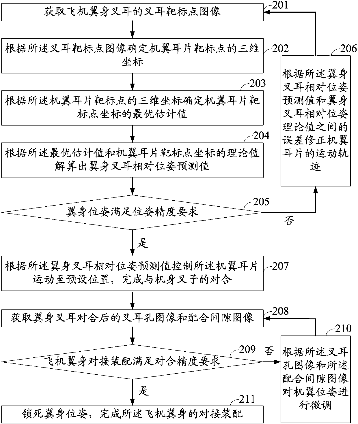
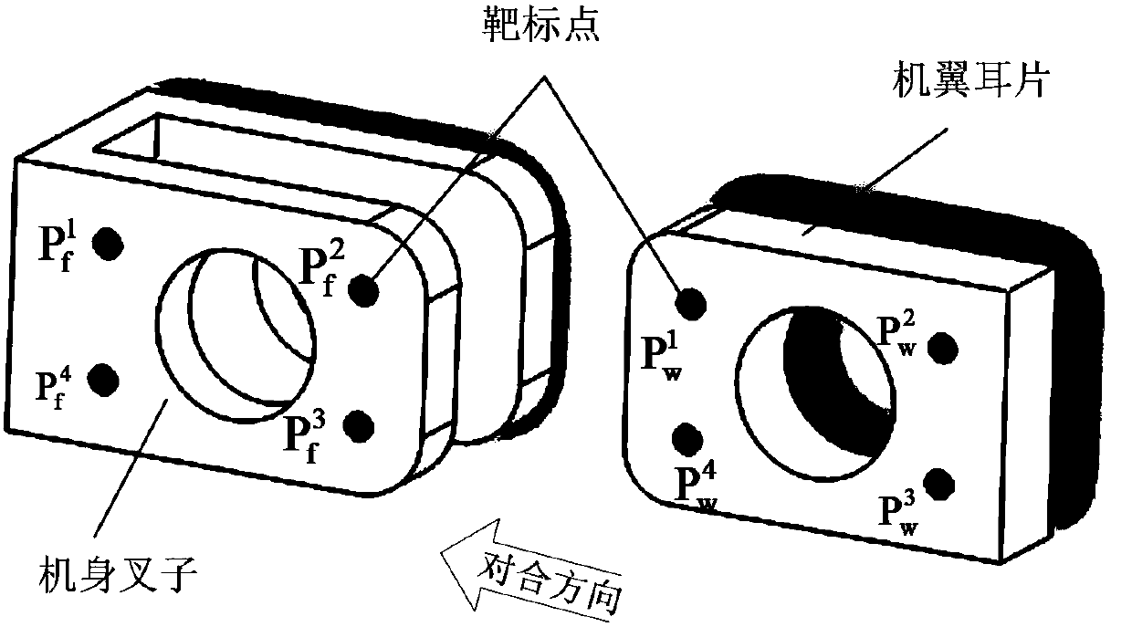
[0078] The purpose of the present invention is to provide an aircraft wing-body docking assembly device, method and system, which can monitor and adjust the relative pose of the wing-body in real time by using a binocular camera to measure the target point of the wing-body fork ear and the characteristics of the joint surface, and can real-time The movement trajectory of the wing lugs is corrected, and the quality and efficiency of the assembly of the wing-body...


PUM


Abstract

The invention discloses an airplane wing body docking assembling device, method and system and discloses a combined measuring method of integrated laser tracker measurement and binocular machine vision on the basis of laser tracker auxiliary assembling; by using a mode of using a laser tracker to measure a wing body attitude-adjusting control point, assistance is provided to realizing wing body pose rough adjustment; and characteristics of a target point and an involution surface of a wing body fork lug are measured by using the binocular machine vision; according to measured values of the characteristics of the target point and the involution surface, the relative pose of a wing body is monitored in real time and finely adjusted to make up shortcomings caused by only using the laser tracker to assist the wing body docking assembling; and therefore, the wing body fork lug docking assembling quality is improved and the assembling efficiency is enhanced.

Description

technical field [0001] The invention relates to the technical field of aircraft intelligent assembly, in particular to an aircraft wing body docking assembly device, method and system. Background technique [0002] The docking assembly of large aircraft parts is the main work content of aircraft assembly, and the docking of aircraft wing and fuselage (abbreviated as aircraft wing body) is an important part of it. The butt joint assembly of the fuselage and wings is usually inseparable from the two important steps of attitude adjustment and inversion, which play a decisive role in the overall quality and efficiency of the assembly. Different from general mechanical products, the object size of the wing-body butt joint assembly is relatively large, which is difficult to measure, and the joint surface is easily deformed, and the manufacturing and installation accuracy is not high. In traditional aircraft wing-to-body docking assembly, workers use a large number of special tool...

Claims


Application Information

Patent Timeline
IPC IPC(8): B64F5/10
CPCB64F5/10
Inventor 朱永国张文博周结华徐雪峰
Owner NANCHANG HANGKONG UNIVERSITY
Learn More