
An auxiliary robot for sheet metal processing

A sheet metal and robot technology, which is applied in the field of sheet metal processing, can solve the problems of being unsuitable for bending small-sized workpieces, easily interfering with the bending machine, and large structural size, achieving no-degree-of-freedom redundancy and occupying a large area Small, easy-to-control effects

Active Publication Date: 2020-02-07
NANJING UNIV OF POSTS & TELECOMM
View PDF8 Cites 0 Cited by
  • Summary
  • Abstract
  • Description
  • Claims
  • Application Information

AI Technical Summary

Problems solved by technology

However, the disadvantages are also very obvious: large structural size, large footprint, slow speed, and inflexibility
[0007] Both of the above two sheet bending automation solutions have the following defects: the axes of the two ends of the wrist joint intersect at one point, which is mainly to facilitate the solution of kinematic equations
In addition, it is suitable for bending large-sized workpieces, and it is easy to interfere with the bending machine when bending small-sized workpieces, so it is not suitable for bending small-sized workpieces at all.

Method used


Image

  • An auxiliary robot for sheet metal processing
  • An auxiliary robot for sheet metal processing
  • An auxiliary robot for sheet metal processing

Examples


Embodiment Construction

[0048] The present invention will be further described in detail below in conjunction with the accompanying drawings and specific preferred embodiments.

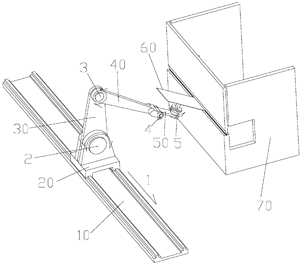
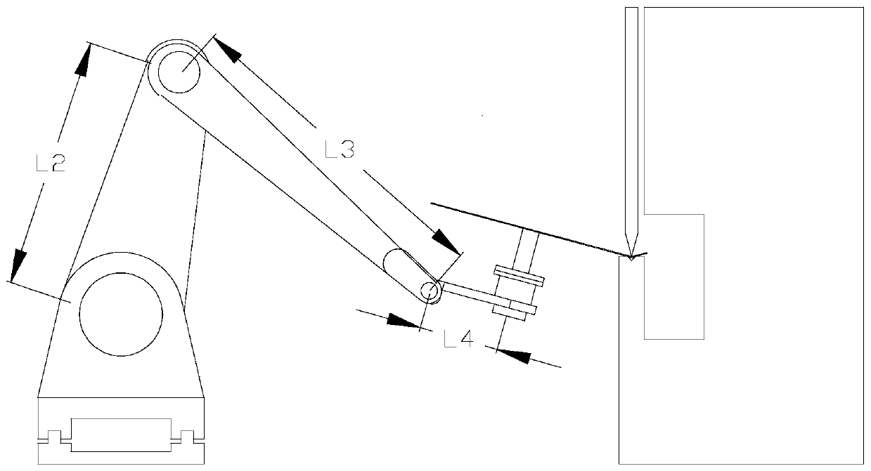
[0049] Such as figure 1 As shown, an auxiliary robot applied to sheet metal processing includes a base 10, a slider 20, a large arm 30, a small arm 40, a forearm 50, a rotating shaft and a clamp.

[0050] The base is linear, the bottom of the slider slides along the base line, and a 1-axis joint is formed between the slider and the base, referred to as 1-axis.

[0051] The top of the slider is hinged to the bottom of the boom through 2 axes, the top of the boom is hinged to the rear end of the forearm through 3 axes, and the front end of the forearm is hinged to the rear end of the forearm through 4 axes.

[0052] The axes of the 1-axis, 2-axis, 3-axis and 4-axis are all parallel to each other.

[0053] The rotating shaft is 5 shafts, the bottom of the rotating shaft is rotationally connected with the front end of the forear...


PUM


Abstract

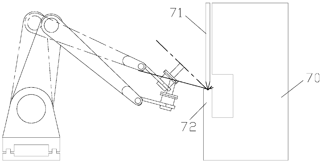
The invention discloses an auxiliary robot applied to metal plate machining. The auxiliary robot applied to metal plate machining comprises a base, a slide block, a large arm, a small arm, a front arm, a rotary shaft and a fixture, wherein the base is linear, and the bottom of the slide block carries out linear slide along the base. The bottom of the rotary shaft is rotationally connected with thefront end of the front arm, the top of the rotary shaft is fixedly connected with the fixture, and the fixture can be detachably connected with a metal plate. According to the auxiliary robot appliedto metal plate machining, compared with the presently common six-axis universal robot, one shaft is omitted, so that cost saving is benefited; and the auxiliary robot applied to metal plate machiningis free from freedom redundancy and simple to control. Meanwhile, the inverse kinematics process of a bending process gives a drive function for each movement joint. The solution formula of each drive angle is programmed into a corresponding program module through C, C++, VB, ST and other high-level programming languages, and movement control for the robot can be realized through directly callingthe program modules from a movement controller.

Description

technical field [0001] The invention relates to the field of sheet metal processing, in particular to an auxiliary robot applied to sheet metal processing. Background technique [0002] In recent years, in the field of sheet metal processing, the application of automated processing technology has gradually become popular. The core technology of sheet metal processing automation lies in the automation of sheet metal bending. Especially for the processing of large-sized and heavy parts, the labor intensity of the workers is high. Usually, two or even several operators are required to complete the processing. The labor intensity is high and the working environment is harsh. The automation solution for plate bending has become the consensus of the industry, with huge market potential and development space. [0003] At present, there are two main solutions for plate bending automation. [0004] 1. Adopt a 6-joint general-purpose robot. For details, refer to the Chinese inventi...

Claims


Application Information

Patent Timeline
Patent Type & Authority Patents(China)
IPC IPC(8): B21D5/00B21D5/02
CPCB21D5/004B21D5/006B21D5/0209B21D5/0281
Inventor 徐丰羽蒋国平
Owner NANJING UNIV OF POSTS & TELECOMM
Learn More