Municipal garden draining structure
A drainage structure and gardening technology, which is applied to drainage structures, waterway systems, water supply devices, etc., and can solve problems such as clogged grid plates
- Summary
- Abstract
- Description
- Claims
- Application Information
AI Technical Summary
Problems solved by technology
Method used
Image
Examples
Embodiment 1
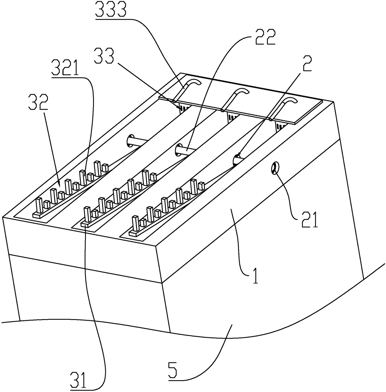
[0030] Embodiment one: a kind of municipal garden drainage structure, such as figure 1 As shown, it includes a grid plate 1 installed on the top of the water pipe 5 , and an anti-blocking mechanism installed on the grid plate 1 to prevent leaves from blocking the grid plate 1 .
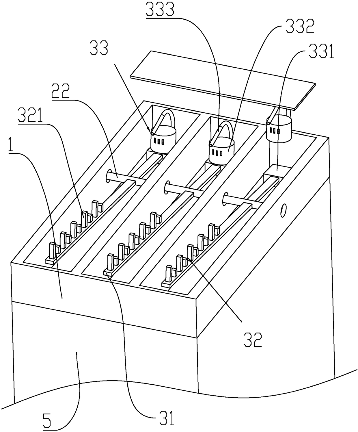
[0031] Such as figure 1 and figure 2 As shown, the blocking stop mechanism is installed on the grid plate 1 through the connecting piece 2 . The connector 2 includes a plurality of bearings 21 fixedly connected to the grid plate 1 , and a rotating shaft 22 is installed on the bearings 21 , wherein the outer ring of the bearing 21 is fixedly connected to the grid plate 1 , and the inner ring is fixedly connected to the rotating shaft 22 .
[0032] Such as figure 2 As shown, there are multiple sets of anti-blocking mechanisms arranged symmetrically on the rotating shaft 22. Each group of anti-blocking mechanisms includes a push rod 31 fixedly connected to the rotating shaft 22. One end of the push ...
Embodiment 2
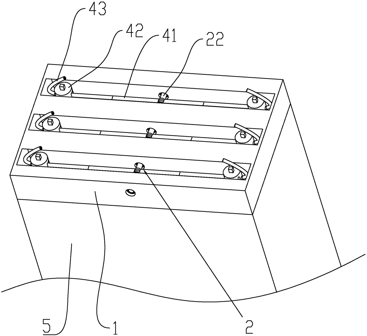
[0035] Embodiment two: a kind of municipal garden drainage structure, such as image 3 and Figure 4 As shown, the difference from Embodiment 1 is that the anti-blocking mechanism is symmetrically provided with multiple groups on the rotating shaft 22, and each group of anti-blocking mechanism includes a floating rod 41 that is rotatably connected to the rotating shaft 22 and can be stretched. The floating rod 41 includes The first rod body 411 and the second rod body 412 , the first rod body 411 is socketed in the second rod body 412 . One end of the rod body 411 away from the rotating shaft 22 is provided with a guide barrel 42, and the guide barrel 42 is fixedly connected with the grid plate 1; a guide groove 43 is provided on the side wall of the guide barrel 42 near the side of the floating rod 41, and the floating rod 41 is away from One end of the rotating shaft 22 passes through the guide groove 43 and is located in the guide barrel 42 . Be positioned at the bottom o...
PUM
 Abstract
Description
Claims
Application Information
 - R&D
- Intellectual Property
- Life Sciences
- Materials
- Tech Scout
- Unparalleled Data Quality
- Higher Quality Content
- 60% Fewer Hallucinations
Browse by: Latest US Patents, China's latest patents, Technical Efficacy Thesaurus, Application Domain, Technology Topic, Popular Technical Reports.
© 2025 PatSnap. All rights reserved.Legal|Privacy policy|Modern Slavery Act Transparency Statement|Sitemap|About US| Contact US: help@patsnap.com


