
Ultrasonic rolling welding machine

An ultrasonic and welding machine technology, which is applied in the field of ultrasonic rolling welding machines, can solve the problems of high requirements for parts processing accuracy, difficulty in ensuring matching accuracy, and difficulty in installation and adjustment.

Pending Publication Date: 2018-08-14
SBT ULTRASONIC TECH CO LTD
View PDF1 Cites 12 Cited by
  • Summary
  • Abstract
  • Description
  • Claims
  • Application Information

AI Technical Summary

Problems solved by technology

This fixing method is not only very difficult during installation and adjustment, but also requires high machining accuracy of the parts, which makes it difficult to ensure the matching accuracy and affects the welding quality.
And when there is wear or replacement of different spindle systems, it is necessary to remove the fixed part and reinstall and adjust it. Not only is the efficiency low, but also parts may need to be replaced

Method used


Image

  • Ultrasonic rolling welding machine
  • Ultrasonic rolling welding machine
  • Ultrasonic rolling welding machine

Examples


Embodiment Construction

[0037] The present invention will be further described below in conjunction with specific embodiment and accompanying drawing, set forth more details in the following description so as to fully understand the present invention, but the present invention can obviously be implemented in many other ways different from this description, Those skilled in the art can make similar promotions and deductions based on actual application situations without violating the connotation of the present invention, so the content of this specific embodiment should not limit the protection scope of the present invention.

[0038] It should be noted that the drawings are only examples, and they are not drawn according to the same scale, and should not be taken as limitations on the protection scope of the actual claims of the present invention.

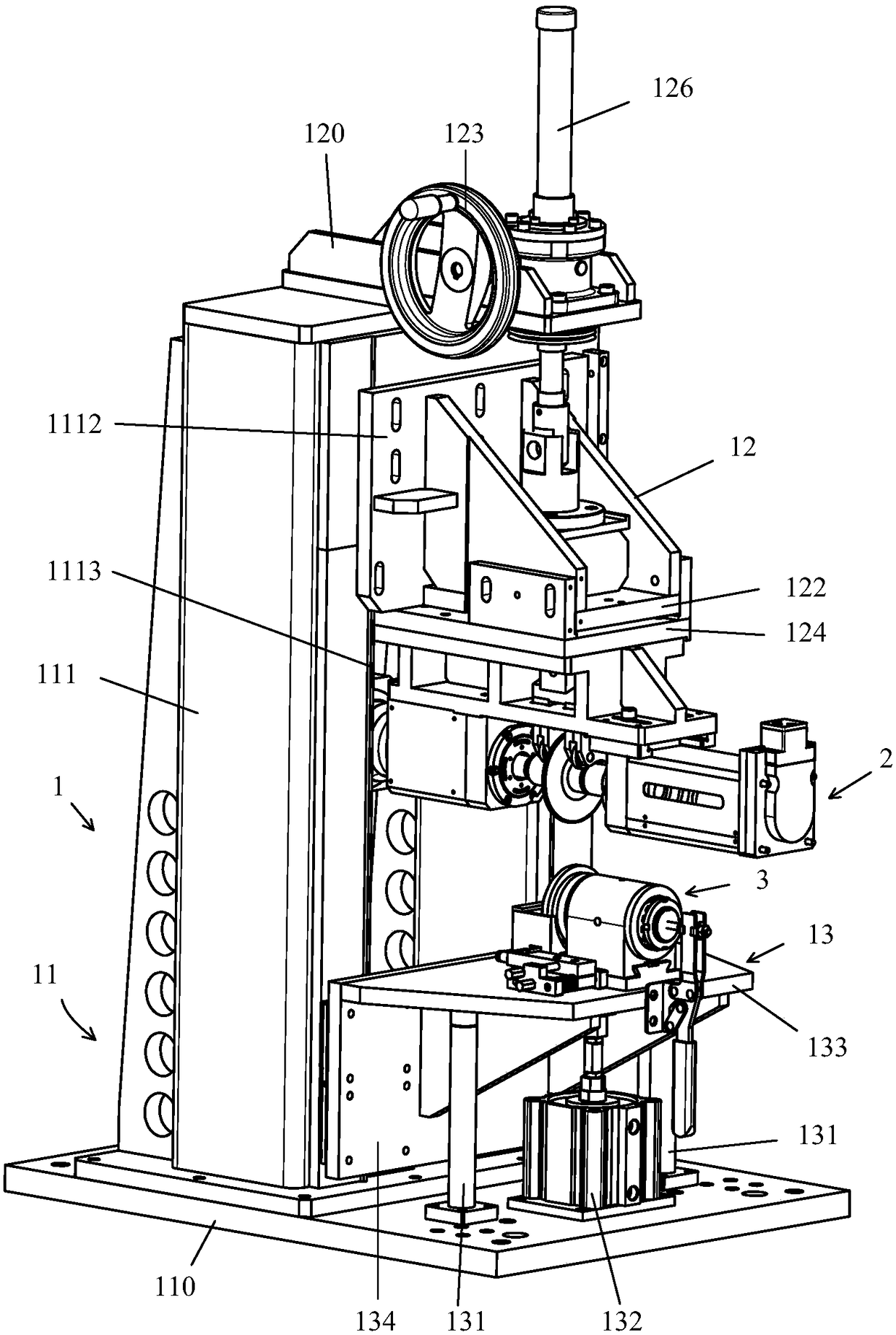
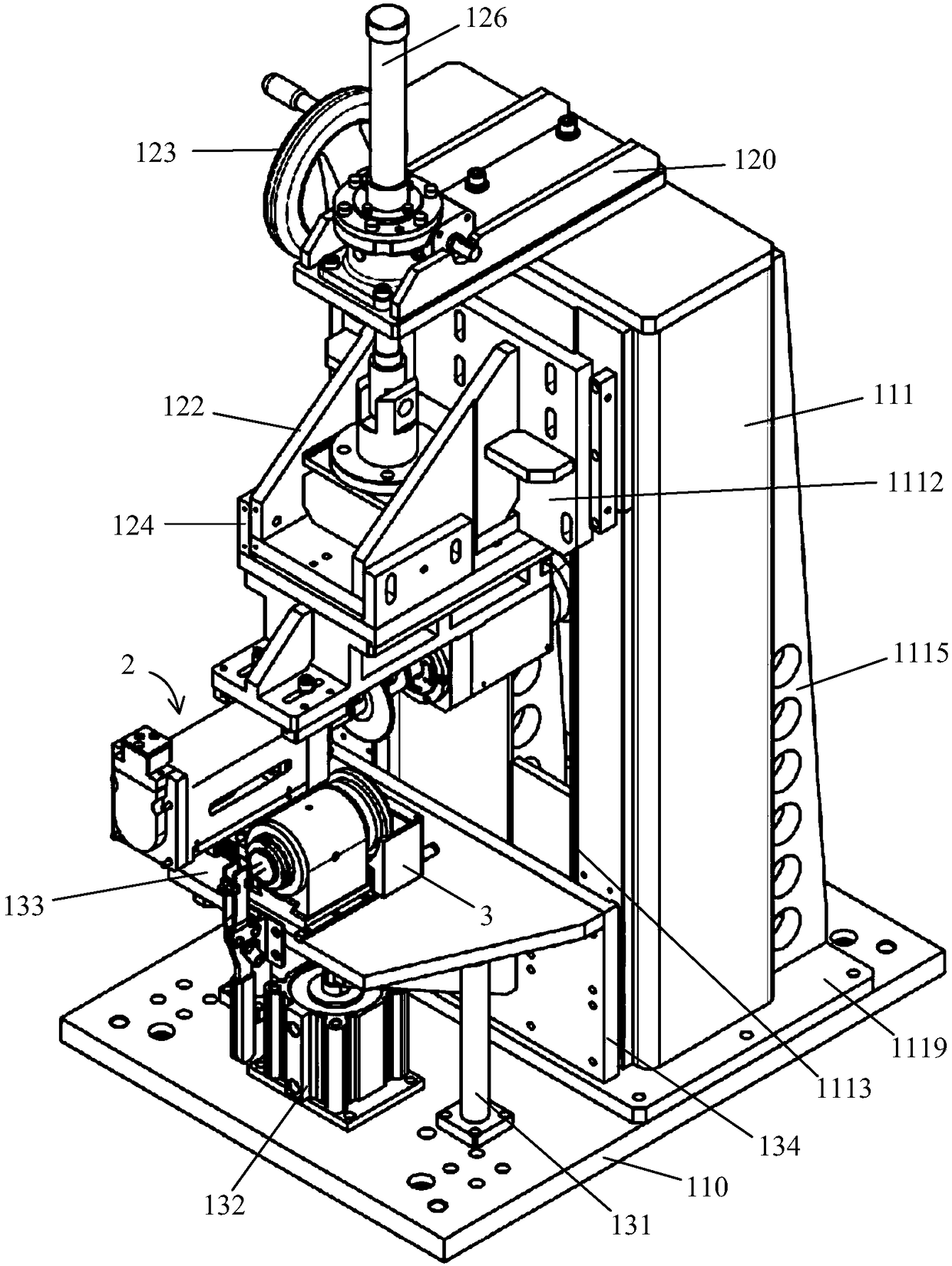
[0039] The ultrasonic rolling welding machine includes a frame, a spindle system and an anvil device, and the frame provides support for the entire machin...


PUM


Abstract

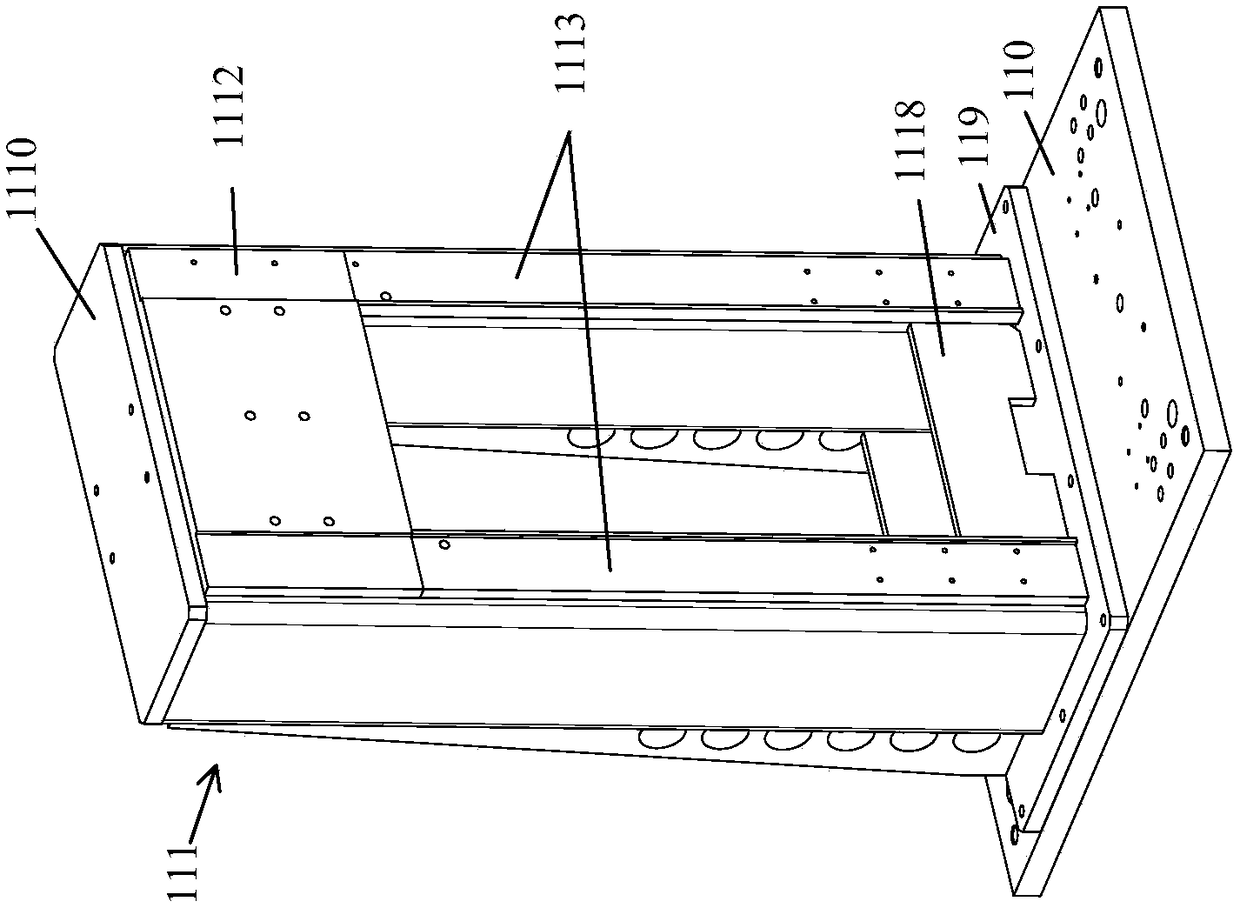
The invention discloses an ultrasonic rolling welding machine which facilitates installing and adjusting between a spindle system and an anvil block device of a welding machine. One side of a verticalframe is provided with a linear guiding rail extending in the vertical direction; an ultrasonic welding head of an upper frame body and an anvil block ring of a lower frame body are arranged in a centering mode; the upper frame body is used for mounting the first part of the spindle system of the upper frame body and the anvil block device of the lower frame body, and the upper frame body is connected to the linear guiding rail of the vertical frame in a coupled mode and can be adjusted up and down along the linear guiding rail; the lower frame body is used for mounting the second part of thespindle system of the upper frame body and the anvil block device of the lower frame body, and the lower frame body is connected to the linear guiding rail of the vertical frame in a coupled mode andcan move up and down along the linear guiding rail; a driving device is mounted on a main frame bottom plate and used for driving the lower frame body to move up and down.

Description

technical field [0001] The invention relates to an ultrasonic rolling welding machine. Background technique [0002] The ultrasonic rolling welding machine includes a spindle system composed of a welding head, an amplitude modulator, a transducer, and an anvil device. Patent document CN106475673A discloses a similar ultrasonic rolling welding machine. During metal seam welding, a mechanism is needed to fix the spindle system and anvil device and complete the welding process. During welding, in order to ensure the welding quality, the welding head of the spindle system needs to have high matching accuracy with the anvil device, and the matching accuracy includes position accuracy, parallelism, etc. In the existing mechanism, both the fixed spindle system and the holding mechanism of the anvil device are fixed, relying on the installation accuracy of the two parts to indirectly ensure the matching accuracy of the two parts. This fixing method is not only very difficult durin...

Claims


Application Information

Patent Timeline
IPC IPC(8): B23K20/10
CPCB23K20/103
Inventor 周宏建石新华段忠福
Owner SBT ULTRASONIC TECH CO LTD
Learn More