Revetment water-stop strip and ecological revetment with same

A technology of water stop strip and limit stop, applied in water conservancy projects, coastline protection, marine engineering and other directions, can solve the problems of difficult construction, high positioning accuracy requirements, easy damage to the pile body, etc., and achieves good effect, convenient construction, Weakening the effect of the crowding effect

Pending Publication Date: 2018-08-10
江苏麦廊新材料科技有限公司
View PDF11 Cites 0 Cited by
  • Summary
  • Abstract
  • Description
  • Claims
  • Application Information

AI Technical Summary

Problems solved by technology

However, in actual construction, the structure of ribs and slots is fine, the construction is difficult, the positioning accuracy is high, and the pile body is easily damaged; multiple identical H-shaped prestressed concrete piles are continuously and closely matched, resulting in large Soil squeeze effect, when driving into the soil, gaps are easily formed between two adjacent piles, which cannot achieve the expected perfect assembly effect, and the effect of retaining soil and water can not be guaranteed

Method used


Image

  • Revetment water-stop strip and ecological revetment with same
  • Revetment water-stop strip and ecological revetment with same
  • Revetment water-stop strip and ecological revetment with same

Examples


Embodiment 1

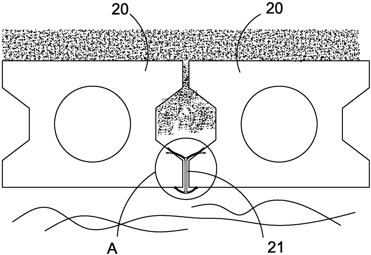
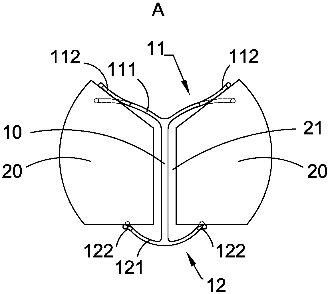
[0031] Embodiment one: as attached figure 1 As shown, a kind of ecological revetment includes a plurality of piles 20 and a plurality of revetment waterstops that are successively sunk in the embankment, and a revetment gap 21 is formed between every two adjacent piles 20, and each revetment waterstop Correspondingly inserted in a corresponding revetment gap 21 . figure 1 The upper side is the side facing the soil, and the lower side is the side facing the water.

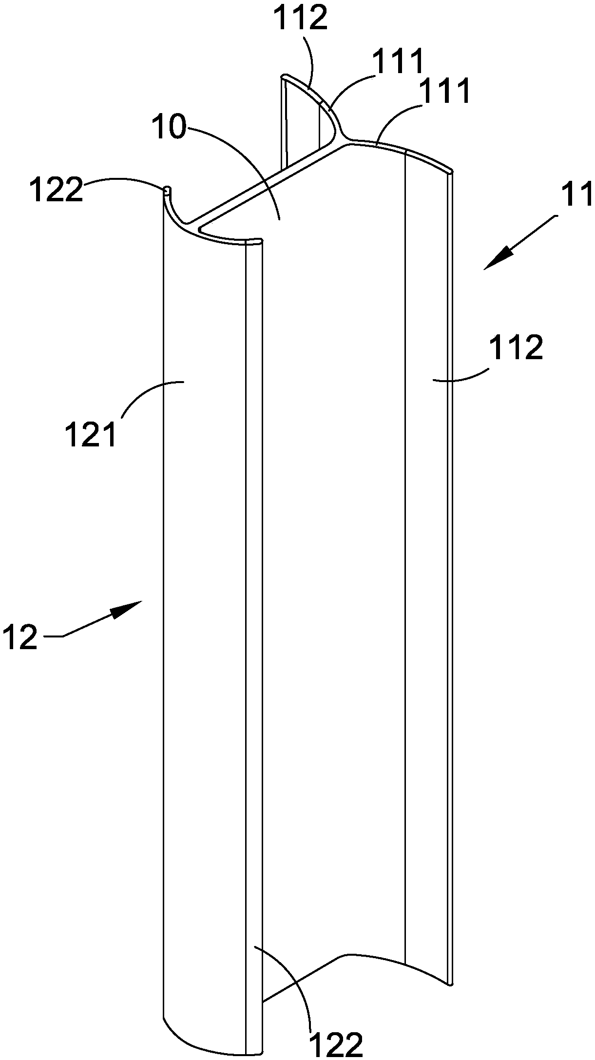
[0032] as attached Figure 1-3 As shown, the revetment waterstop strip includes a slit strip 10 located in the middle for being inserted into the revetment gap 21, a first stopper 11 located at one side of the slit strip 10 to prevent the slit strip 10 from breaking away from the revetment gap 21, and a The opposite side of the seam strip 10 prevents the seam strip 10 from breaking away from the second stopper 12 of the revetment gap 21, as attached figure 1 , 2 As shown, the first limit stop 11 and the second l...

Embodiment 2

[0038] Embodiment two, as attached Figure 4 As shown, the difference between the second embodiment and the first embodiment is that the second stopper 12 of the revetment waterstop strip has no flexible part. The outer surface of the second limit stop main body 121 is an arc-shaped surface, which plays a decorative role. However, in order to play a decorative role, the outer surface of the second limit stop body 121 is not limited to a curved surface, but can also be other, such as a wavy surface.

[0039]The slit strip 10, the first stopper main body 111 and the second stopper main body 121 are made of metal materials, and the first stopper flexible part 112 is wrapped on the slit strip 10 and the first stopper through extrusion processing. Block the main body 111. Arch extrusion processing of metal and plastics also belongs to the prior art process and will not be described in detail.

Embodiment 3

[0040] Embodiment three, as attached Figure 5 As shown, the difference between the third embodiment and the first embodiment is that the second stopper 12 of the revetment water-stop strip has no flexible part. The outer surface of the second limit stop main body 121 is an arc-shaped surface, which plays a decorative role. However, in order to play a decorative role, the outer surface of the second limit stop body 121 is not limited to a curved surface, but can also be other, such as a wavy surface.


PUM


Abstract

The invention discloses a revetment water-stop strip and an ecological revetment with the same. The revetment water-stop strip comprises a gap inserting strip which is located on the middle portion and can be inserted in a revetment gap, a first limiting baffle located on one side portion of the gap inserting strip for preventing the gap inserting strip from breaking away from the revetment gap and a second limiting baffle located on the other opposite side portion of the gap inserting strip for preventing the gap inserting strip from breaking away from the revetment gap. At least one of the first limiting baffle and the second limiting baffle is provided with a flexible portion which is elastically deformable. The revetment water-stop strip is inserted into the revetment gap existing between pile bodies, at least one of the first limiting baffle and the second limiting baffle is provided with the flexible portion which is elastically deformable, and the flexible portion can be elastically deformed under the action of pressure and abuts against the pile bodies on both sides, so that the functions of retaining soil and stopping water are achieved, the construction is more convenient, and the effects of retaining soil and stopping water are good.

Description

technical field [0001] The invention relates to a revetment and water-stop strip and an ecological revetment with the revetment and water-stop strip. Background technique [0002] In the prior art, such as the ecological environment-friendly embankment protection wall disclosed in the patent publication CN105625257A and the H-type prestressed concrete pile used for the protection wall, [0003] An H-type prestressed concrete pile is disclosed, the cross section of the H-type prestressed concrete pile is H-shaped formed by two flanges and a web connecting the two flanges, and the two sides of the flanges are respectively provided with ribs and slots. A plurality of identical H-shaped prestressed concrete piles are inserted into the soil, and two adjacent H-shaped prestressed concrete piles are inserted and matched through convex ribs and slots, ideally forming a revetment wall to protect the river embankment. However, in actual construction, the structure of ribs and slots ...

Claims


Application Information

Patent Timeline
Patent Type & Authority Applications(China)
IPC IPC(8): E02B3/12E02B3/16
CPCE02B3/12E02B3/16
Inventor 吴健陈铖孙亮
Owner 江苏麦廊新材料科技有限公司
Why Eureka
Try Eureka