Power head capable of adjusting cutter angle

A technology of tool angle and power head, applied in the field of power head, can solve the problems of difficult to improve machining accuracy, weak fixing effect, large oscillation force, etc., to reduce difficulty and assembly difficulty, small components and space occupied, and tolerance range Increased effect

Pending Publication Date: 2018-08-10
佛山市顺德区凌氏机电设备有限公司
View PDF13 Cites 1 Cited by
  • Summary
  • Abstract
  • Description
  • Claims
  • Application Information

AI Technical Summary

Problems solved by technology

[0002] The traditional CNC power head is generally fixed on the base, column or sliding table to complete the drilling, milling, boring and other processes with radial or axial feed. For the suspended power head, generally only simple However, in the actual production process, when encountering workpieces with complex shapes, it is hoped that the same power head can be used to rotate the angle to achieve multiple Processing of profiles with different angles
[0003] Some solutions to this problem have been proposed in the prior art, some of which have a structure for manually adjusting the angle, but the manual adjustment is inefficient and depends on the proficiency of the operator, and the rotation accuracy is difficult to guarantee; others are driven by mechanical rotation. There are also many defects in the scheme of the tool on the head. For example, in the utility model patent of the CNC rotary power head with the notification number CN204221389 and the angle adjustment mechanism of the power head with the notification number CN205520488U, the first servo motor is used to drive the power head to rotate along the guide groove. way to adjust the angle of the power head
However, the rotation achieved in this way requires an additional guide groove to standardize the rotation track of the power head, which makes the volume of the overall equipment larger; and because the driven gear and ring gear need to be concentric with the guide groove, the guide groove The greater the distance between the position and the ring gear of the driving gear, the greater the possibility of misalignment caused by tolerances during manufacturing; after long-term use, the guide groove and the guide block wear each other, and the guide block and guide groove need to be replaced frequently , increasing the later maintenance cost
In terms of positioning structure, the use of springs to lock and rotate the power head tool has a weak fixing effect. When the power head tool rotates at high speed to process products, the oscillation force generated is relatively large, and the scalability of the spring makes it difficult to meet the needs. The tightness of the power head makes the tool of the power head easy to shake during work, and it is difficult to improve the machining accuracy.

Method used


Image

  • Power head capable of adjusting cutter angle
  • Power head capable of adjusting cutter angle
  • Power head capable of adjusting cutter angle

Examples


Embodiment Construction

[0026] A kind of adjustable tool angle power head of the present invention is illustrated in conjunction with the accompanying drawings, as can be seen from the figure:

[0027] As embodiment 1 of the present invention, as attached Figure 1-3 Shown:

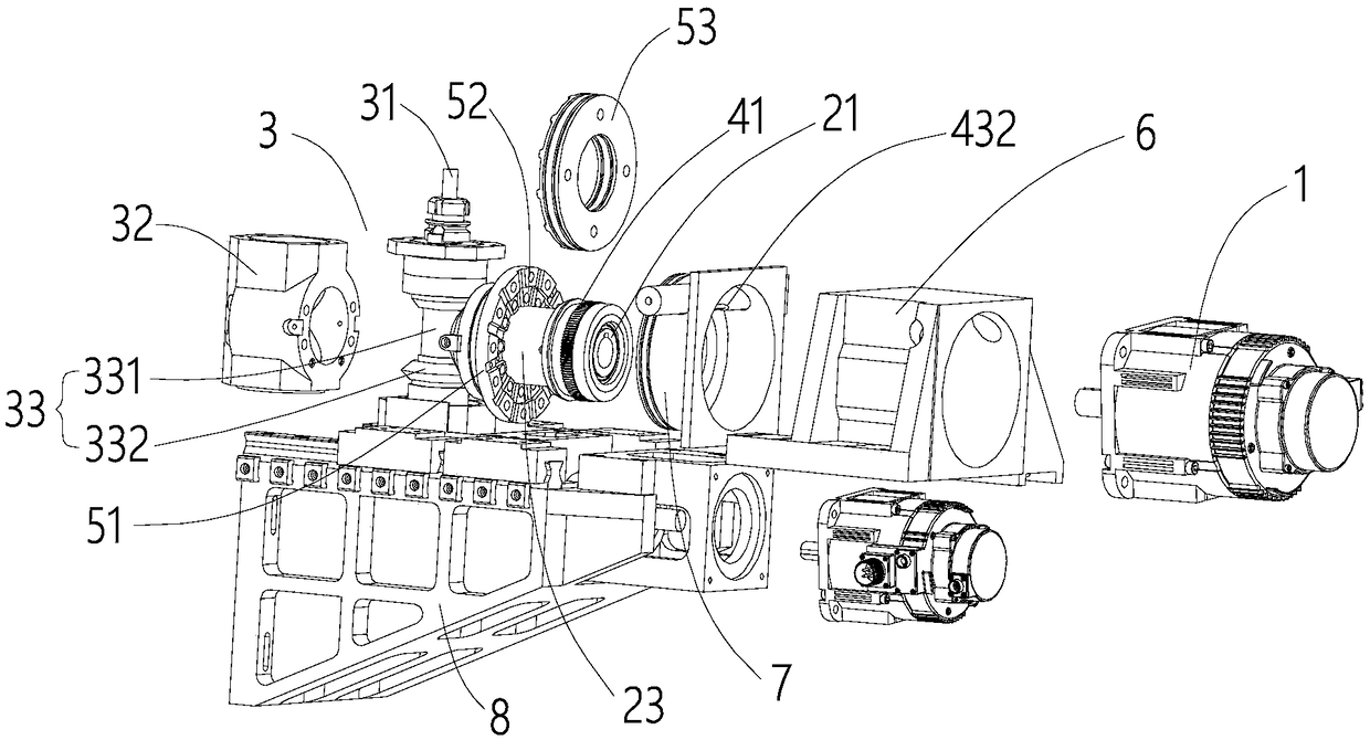
[0028] A power head capable of adjusting the angle of the cutter, comprising a first motor 1, a shaft assembly and a cutter 3, the first motor 1 is connected through the shaft assembly and drives the cutter head 31 of the cutter 3 to rotate;

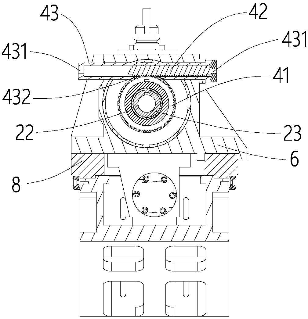
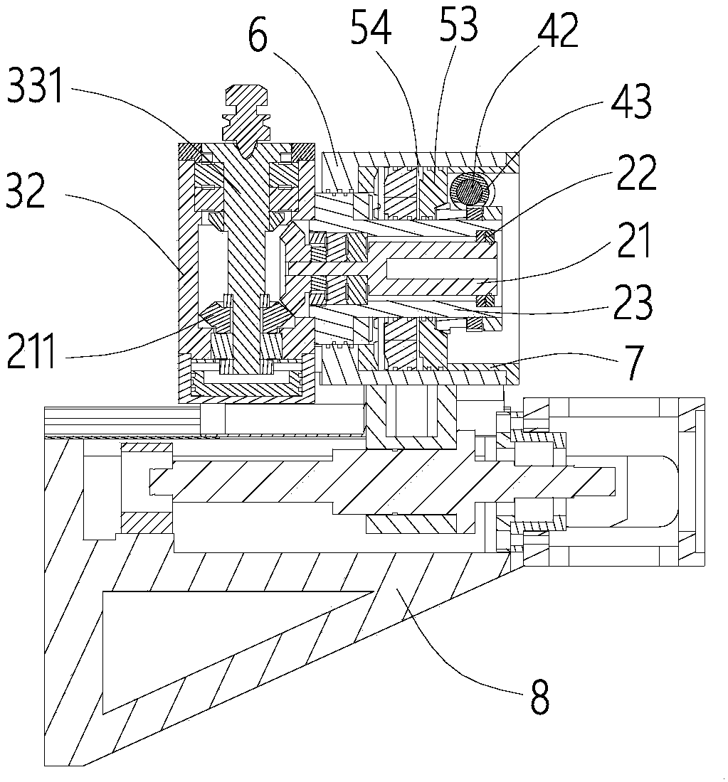
[0029]The shaft assembly includes a main shaft 21, a bearing 22 and a shaft sleeve 23, the main shaft 21 and the tool 3 adopt space gear transmission, and the first motor 1 drives the cutter head 31 of the tool 3 to rotate through the main shaft 21 The bearing 22 supports the main shaft 21 to rotate in the bushing 23, and the bushing 23 is connected and fixed to the tool 3;

[0030] It also includes an indexing gear 41 and a rack 42, the indexing gear 41 and the rack 42 mesh with each ot...


PUM


Abstract

The invention discloses a power head capable of adjusting the cutter angle. The power head comprises a first motor, a shaft component and a cutter, the first motor connects and drives a cutter head ofthe cutter to rotate through the shaft component, the shaft component comprises a main shaft and a shaft sleeve, the main shaft is in space gear transmission with the cutter, the first motor drives the cutter head of the cutter to rotate through the main shaft, the main shaft is installed inside the shaft sleeve, the shaft sleeve is connected and fixed with the cutter, the power head further comprises an indexing gear and a toothed strip, the indexing gear is engaged with the toothed strip each other and is arranged and fixed to the shaft sleeve in a sleeved manner, and the indexing gear is driven by the toothed strip to drive the cutter to perform indexing rotating around the axis of the main shaft. The power head capable of adjusting the cutter angle is compact in structure, and the machining angle of the cutter can be conveniently and accurately adjusted without arrangement of a guide rail.

Description

technical field [0001] The invention relates to the field of numerically controlled cutting tools, in particular to a power head capable of adjusting the angle of the cutting tool. Background technique [0002] The traditional CNC power head is generally fixed on the base, column or sliding table to complete the drilling, milling, boring and other processes with radial or axial feed. For the suspended power head, generally only simple However, in the actual production process, when encountering workpieces with complex shapes, it is hoped that the same power head can be used to rotate the angle to achieve multiple Processing of profiles with different angles. [0003] Some solutions to this problem have been proposed in the prior art, some of which have a structure for manually adjusting the angle, but the manual adjustment is inefficient and depends on the proficiency of the operator, and the rotation accuracy is difficult to guarantee; others are driven by mechanical rotat...

Claims


Application Information

Patent Timeline
Patent Type & Authority Applications(China)
IPC IPC(8): B23Q5/10B23Q15/26
CPCB23Q5/10B23Q15/26
Inventor 凌俊
Owner 佛山市顺德区凌氏机电设备有限公司
Why Eureka
Try Eureka