Continuous transonic wind tunnel semi-flexible wall nozzle throat block vertical space electric drive device

An electric drive, vertical space technology, applied in the field of continuous transonic wind tunnel test, can solve the problems of large swing mass, low reliability, slow response, etc., to achieve increased effective component force, low maintenance cost, and reduced difficulty Effect

Active Publication Date: 2021-11-09
中国空气动力研究与发展中心设备设计及测试技术研究所 +1
View PDF0 Cites 0 Cited by
  • Summary
  • Abstract
  • Description
  • Claims
  • Application Information

AI Technical Summary

Problems solved by technology

[0003] The technical problem to be solved by the present invention is to provide a continuous transonic wind tunnel nozzle section semi-soft-walled throat block vertical space type electric drive device, so that it can complete the large throat block in a limited vertical space. The ability to adjust the position and posture; solve the inevitable problem of large swinging mass in the "frame swing" working mode of common semi-flexible nozzles; solve the problems of large energy consumption and slow response in the traditional throat block drive mode, Provide low energy consumption, high response speed, innovative, safe and reliable electric drive mode of throat block section; realize multi-motor synchronous drive and coordinated control, and improve the accuracy of throat block position control based on coupled motion parallel mechanism; innovative design of motor drive The precision transmission system and layout structure make the throat block driving device have the advantages of convenient installation, reliable operation and long service life; the throat block section has the ability to adjust six degrees of freedom in space, and then the driving device can actively resist lateral force, Solve the huge wear and low reliability caused by the traditional way of relying on forced guidance to overcome lateral force

Method used


Image

  • Continuous transonic wind tunnel semi-flexible wall nozzle throat block vertical space electric drive device
  • Continuous transonic wind tunnel semi-flexible wall nozzle throat block vertical space electric drive device
  • Continuous transonic wind tunnel semi-flexible wall nozzle throat block vertical space electric drive device

Examples


Embodiment 1

[0043] The vertical space type electric drive device of the semi-flexible throat block of the nozzle section of the continuous transonic wind tunnel is characterized in that:

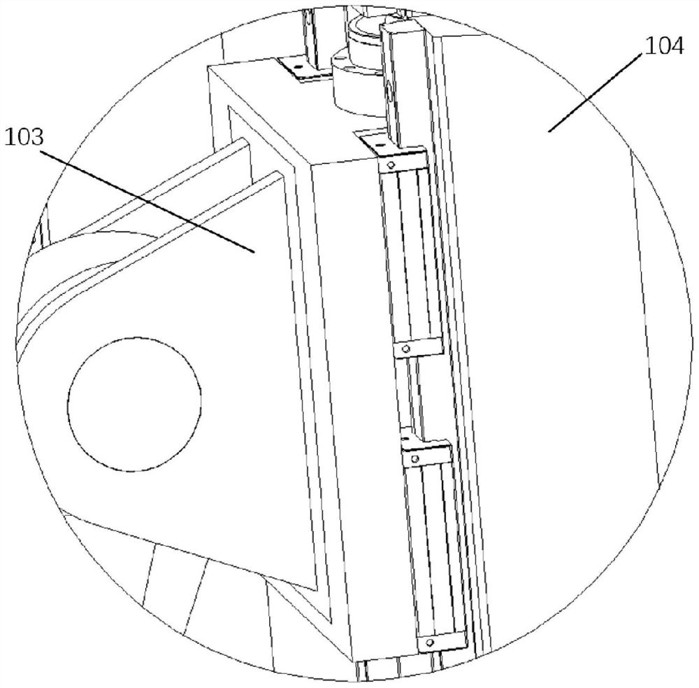
[0044] The device includes several execution units C, and the execution unit C includes: a drive rod unit, a slide table, a guide unit, and a drive unit. The device includes a mount (10), which is a flat plate placed vertically. The device includes a throat block (9), which is located directly below the mounting base (10);

[0045] The guide unit in each executive unit C comprises a guide rail arranged in parallel in the vertical direction and a base for installing the guide rail, the guide rail base is fixedly installed on the corresponding mounting seat (10), and a displacement sensor is fixedly installed next to the guide unit; The drive unit in each execution unit C drives the corresponding sliding table to move in the vertical direction, and the motor in the drive unit is fixedly installed on the ...

Embodiment 2

[0048] A continuous transonic wind tunnel semi-flexible wall surface nozzle throat block vertical space type electric drive device as described in Embodiment 1 is characterized in that the continuous transonic wind tunnel semi-flexible wall surface nozzle throat block vertical space Type electric drives include:

[0049] According to the requirements of the wind tunnel test, there are 3 mounting seats (10) for vertically arranging the driving unit;

[0050] The number of execution units C arranged in the vertical direction determined according to the requirements of the wind tunnel test is 8 groups;

[0051] According to the requirements of the wind tunnel test, it is determined that the driving unit of each group of execution units C is driven by a motor, driven by a screw, and can also be directly driven by a motor electric cylinder;

[0052] According to the requirements of the wind tunnel test, each group of executive units C includes 1 set of guide units, and 1 set of gu...

Embodiment 3

[0057] As described in the first and second embodiments, a continuous transonic wind tunnel semi-flexible wall surface nozzle throat block vertical space type electric drive device is characterized in that the continuous transonic wind tunnel semi-flexible wall surface nozzle throat block vertical Direct space electric drives include:

[0058] The throat block drive rod unit under each execution unit C is connected to the throat block by a ball pair connection, and the drive rod unit is respectively connected to the corresponding throat block section slide table and throat block section (9). The spherical pair is based on the actual working conditions. The required adjustment angle can be determined as a ball joint or a rod end bearing;

[0059]According to the requirements of the wind tunnel test, the position distribution of the connection points between the drive rod unit and the throat block section in each actuator unit C is determined. The number of drives is greater tha...


PUM


Abstract

A continuous transonic wind tunnel semi-flexible wall surface nozzle throat block vertical space type electric drive device, which realizes precise control of the predetermined pose of the nozzle throat block. The device innovatively uses a parallel mechanism to realize six-degree-of-freedom control of the throat block, which can actively control and eliminate the additional load acting on the throat block. It includes a drive unit arranged vertically and driven by a motor; a guide unit composed of multiple sets of guide rails; a transmission unit composed of a throat slide table, a slider, a drive rod and a spherical pair; an outer frame and a throat block mounting plate composed of support units. The continuous transonic wind tunnel semi-flexible wall surface nozzle throat block vertical space electric drive device forms a parallel mechanism with redundant degrees of freedom through multiple drives to drive the throat block to reach a predetermined pose, and ensure its accuracy and molding stability. sex.

Description

technical field [0001] The invention relates to the technical field of continuous transonic wind tunnel tests, in particular to a six-degree-of-freedom position and posture adjustment mechanism in the semi-soft wall throat block space of the continuous transonic wind tunnel nozzle section. Through the coupling movement and joint control of six groups of effective vertical drives (multiple groups of follow-up vertical drives can be added), the complete control of the six degrees of freedom of the throat block is realized. The device is mainly used for the driving control of the throat block of the semi-flexible nozzle of the continuous transonic wind tunnel. Background technique [0002] The wind tunnel is an important test device used to verify whether the aerodynamic shape of various types of aerospace vehicles and high-speed EMUs is reasonable. Its main principle is to simulate the external gas flow field characteristics (Mach number, Reynolds number, etc.) number, Prandt...

Claims


Application Information

Patent Timeline
Patent Type & Authority Patents(China)
IPC IPC(8): G01M9/04
CPCG01M9/04
Inventor 王海吴高旭陈振华谢志江王超琪皮阳军廖文林宋代平胡兴龙张浩刘飞
Owner 中国空气动力研究与发展中心设备设计及测试技术研究所
Why Eureka
Try Eureka