
Visual blood collection needle

A blood collection needle and needle seat technology, applied in the field of visual blood collection needles, can solve the problems of not being able to clearly observe the blood flow, affecting the accuracy of the test results, and not achieving visual effects, etc., to improve the accuracy of blood samples, The indicated process is clear and rapid, and the effect of reducing the degree of red blood cell damage

Pending Publication Date: 2018-08-03
威海赛威医疗科技有限公司
View PDF0 Cites 2 Cited by
  • Summary
  • Abstract
  • Description
  • Claims
  • Application Information

AI Technical Summary

Problems solved by technology

In addition, because the cavity of the blood return chamber consumes the vacuum degree of the vacuum blood collection tube, the blood collection volume of the first vacuum blood collection tube will be obviously insufficient, and the insufficient blood collection volume will affect the accuracy of some test results
In the blood collection process, the blood flows into the blood collection tube through the needle tube in principle, but the current blood return needle has a relatively large inner cavity, and the blood enters the cavity and flows into the blood collection tube through a circle. After the blood collection, a certain amount of blood remains in the cavity, causing blood waste.
At present, when the volume of the blood return chamber of the blood collection needle is too small, the blood flow cannot be clearly observed, and the visual effect cannot be achieved.

Method used


Image

  • Visual blood collection needle
  • Visual blood collection needle
  • Visual blood collection needle

Examples


Embodiment Construction

[0029] The present invention will be further described below in conjunction with the accompanying drawings and specific embodiments, so as to help understand the content of the present invention. The methods used in the present invention are conventional production methods unless otherwise specified; the raw materials used are conventional commercially available products unless otherwise specified.

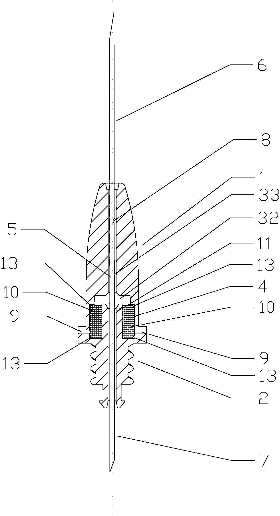
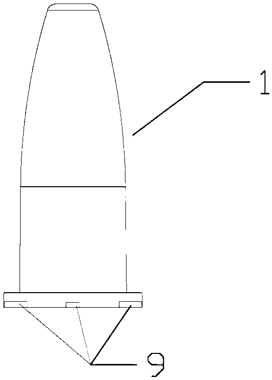
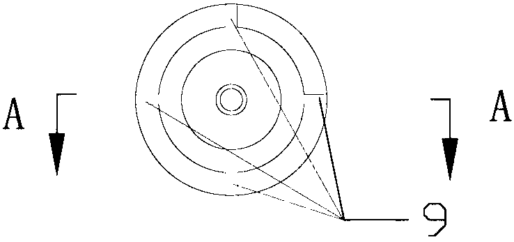
[0030] Depend on Figure 1 to Figure 9 As shown, a visual blood collection needle provided by the present invention is provided with a transparent plastic needle holder and a stainless steel needle tube 5 with needle points at both ends; Seat 2, the needle seat 1 at the puncture end is provided with a hollow blood return chamber, the upper part of the blood return chamber is provided with a return blood vessel 31, and the lower part of the blood return chamber is provided with a lower end return blood chamber 2, and the return blood vessel 31 and the lower end return blood chamber...


PUM


Abstract

The invention relates to a visual blood collection needle. The visual blood collection needle solves the technical problems that for visual blood collection needles in the prior art, the blood returning chambers are large, the indication process is unclear, the speed is low, the blood is wasted, and the accuracy of blood collection samples is low. The visual blood collection needle is provided with a transparent needle base and a stainless steel needle tube with needle tips at the two ends; a blood returning chamber is provided with a blood returning tube and a lower-end blood returning chamber which define an inverted T shape; the two ends of the stainless steel needle tube are in fixed and sealed connection with the two ends of the needle base respectively, and a gap is firmed between the stainless steel needle tube and the blood returning tube; a blood returning hole runs through the stainless steel needle tube in the blood returning tube and is communicated with the blood returningtube; a ventilation hole runs through the side wall of a filling chamber and is communicated with the exterior; the filling chamber is further internally provided with a filtering core and filled with the filtering core, and the filtering core is made of materials which can be ventilated when dried and sealed when expanded by liquid. The visual blood collection needle is widely applied to the field of medical instruments.

Description

technical field [0001] The invention relates to the field of medical devices, in particular to a visual blood collection needle. Background technique [0002] It can be seen that the function of the blood collection needle for returning blood is that the operator can judge whether the puncture blood vessel is successful or not in an intuitive way, which avoids the fuzzy subjective judgment that relies on the feeling in the original blood collection operation, effectively improves the work efficiency and the success rate of blood collection, and reduces the pain of the patient. However, the existing blood collection needles with visible blood return still have disadvantages: some products with relatively simple structures can see blood return after puncture to obtain instructions. The process is not clear and fast, which hinders the improvement of blood collection work efficiency. In order to clearly observe the return of blood, it is necessary to set the observation chamber ...

Claims


Application Information

Patent Timeline
Patent Type & Authority Applications(China)
IPC IPC(8): A61B5/153
CPCA61B5/150206A61B5/150396A61B5/150419A61B5/150427A61B5/153
Inventor 姜全国史珍妮姜小蕾
Owner 威海赛威医疗科技有限公司
Learn More