
Unmanned aerial vehicle pollination device and method thereof

A technology for pollination devices and unmanned aerial vehicles, which is applied in launching devices, botanical equipment and methods, and unmanned aerial vehicles, etc. It can solve problems such as limited improvement in labor efficiency, ineffective pollination operations, and pollen landing on the ground. The effect of reducing spillage, improving efficiency, and improving utilization

Active Publication Date: 2018-08-03
NANJING AGRI MECHANIZATION INST MIN OF AGRI
View PDF8 Cites 10 Cited by
  • Summary
  • Abstract
  • Description
  • Claims
  • Application Information

AI Technical Summary

Problems solved by technology

Human pollination is labor-intensive and uneven, and due to the short pollination cycle, it is often impossible to complete the pollination within the specified time; mechanical pollination generally includes hand-held, ground-walking and drone pollination. Hand-held pollination is mainly For commercial crops, the improvement of labor efficiency is limited. Due to the influence of farmland terrain and crop types (hills, paddy fields, etc.), walking pollination on the ground is difficult to get to the ground.
[0003]The existing drone pollination technology generally uses the downwash airflow generated by the rotor to blow the pollen away and distribute it in space. Fans are installed below to spread the pollen in the horizontal direction. These two methods improve the pollination efficiency, but because they both use the downwash airflow of the rotor to blow off the pollen, part of the pollen falls to the ground, and the downwash airflow will carry the pollen to the ground. To the sky above the female parent, pollination cannot be carried out effectively

Method used


Image

  • Unmanned aerial vehicle pollination device and method thereof
  • Unmanned aerial vehicle pollination device and method thereof
  • Unmanned aerial vehicle pollination device and method thereof

Examples


Embodiment Construction

[0036] The present invention will be further described below in conjunction with the accompanying drawings and specific preferred embodiments.

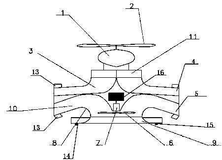
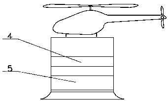
[0037] An unmanned aerial vehicle pollination device is characterized in that it includes an unmanned aerial vehicle 1, a rotor 2 is arranged above the unmanned aerial vehicle 1, and an air outlet flow channel 3 is suspended below the unmanned aerial vehicle 1. The air outlet channel 3 is composed of two mutually independent and symmetrical air outlet channels. The air outlet channel is composed of an upper curved plate and a lower curved plate. The air inlet of the air outlet channel 3 is vertically upward. The air outlet 4 of the air outlet flow channel 3 faces both sides horizontally, and the powder outlet flow channel 10 is arranged under the air outlet flow channel 3, and the powder outlet flow channel 10 is composed of two mutually symmetrical powder outlet channels, The powder outlet is composed of an upper curve and a lower cu...


PUM


Abstract

The invention belongs to an unmanned aerial vehicle pollination device and a method thereof. The unmanned aerial vehicle pollination device comprises an unmanned aerial vehicle, wherein a rotor wing is arranged above the unmanned aerial vehicle; an air outlet flow passage is hung under the unmanned aerial vehicle; a pollen outlet passage is arranged under the air outlet passage; an air outlet of the air outlet flow passage is arranged above a pollen outlet of the pollen outlet flow passage; the air outlet and the pollen outlet are in horizontal arrangement; an air suction fan is arranged at apollen inlet of the pollen outlet flow passage; an air inlet of the air outlet flow passage is arranged under the rotor wing. The unmanned aerial vehicle pollination device can suck the pollen and horizontally spray out the pollen to the two sides of the unmanned aerial vehicle; the pollen can be diffused to a wider space through an airflow sprayed out from the air outlet. The unmanned aerial vehicle pollination method can improve the pollen utilization rate and can improve the artificial pollination efficiency.

Description

technical field [0001] The invention relates to the technical field of agricultural planting, in particular to an unmanned aerial vehicle pollination device and method thereof. Background technique [0002] During the growth process of crops, assisted pollination is often required. The current artificial assisted pollination mainly includes manpower and mechanical methods. Human pollination is labor-intensive and uneven, and due to the short pollination cycle, it is often impossible to complete the pollination within the specified time; mechanical pollination generally includes hand-held, ground-walking and drone pollination. Hand-held pollination is mainly It is used for commercial crops, and the improvement of labor efficiency is limited. Due to the influence of farmland terrain and crop types (hills, paddy fields, etc.), ground walking pollination is difficult to get to the ground. [0003] The existing UAV pollination technology generally uses the downwash airflow gener...

Claims


Application Information

Patent Timeline
Patent Type & Authority Applications(China)
IPC IPC(8): A01H1/02B64D1/18
CPCA01H1/02B64D1/18A01H1/027B64U10/00
Inventor 丁素明薛新宇顾伟周立新孙竹蔡晨秦维彩陈晨
Owner NANJING AGRI MECHANIZATION INST MIN OF AGRI
Learn More