Dual antenna wireless communication device in load control system

A technology of a wireless communication device and a load control system, which is used in wireless communication, antenna grounding devices, and devices that enable antennas to work in different frequency bands at the same time.

Active Publication Date: 2018-07-31
LUTRON TECH CO LLC
View PDF17 Cites 0 Cited by
  • Summary
  • Abstract
  • Description
  • Claims
  • Application Information

AI Technical Summary

Problems solved by technology

The spacing between antennas can be a limiting factor in the size and form factor of wireless control devices

Method used


Image

  • Dual antenna wireless communication device in load control system
  • Dual antenna wireless communication device in load control system
  • Dual antenna wireless communication device in load control system

Examples


Embodiment Construction

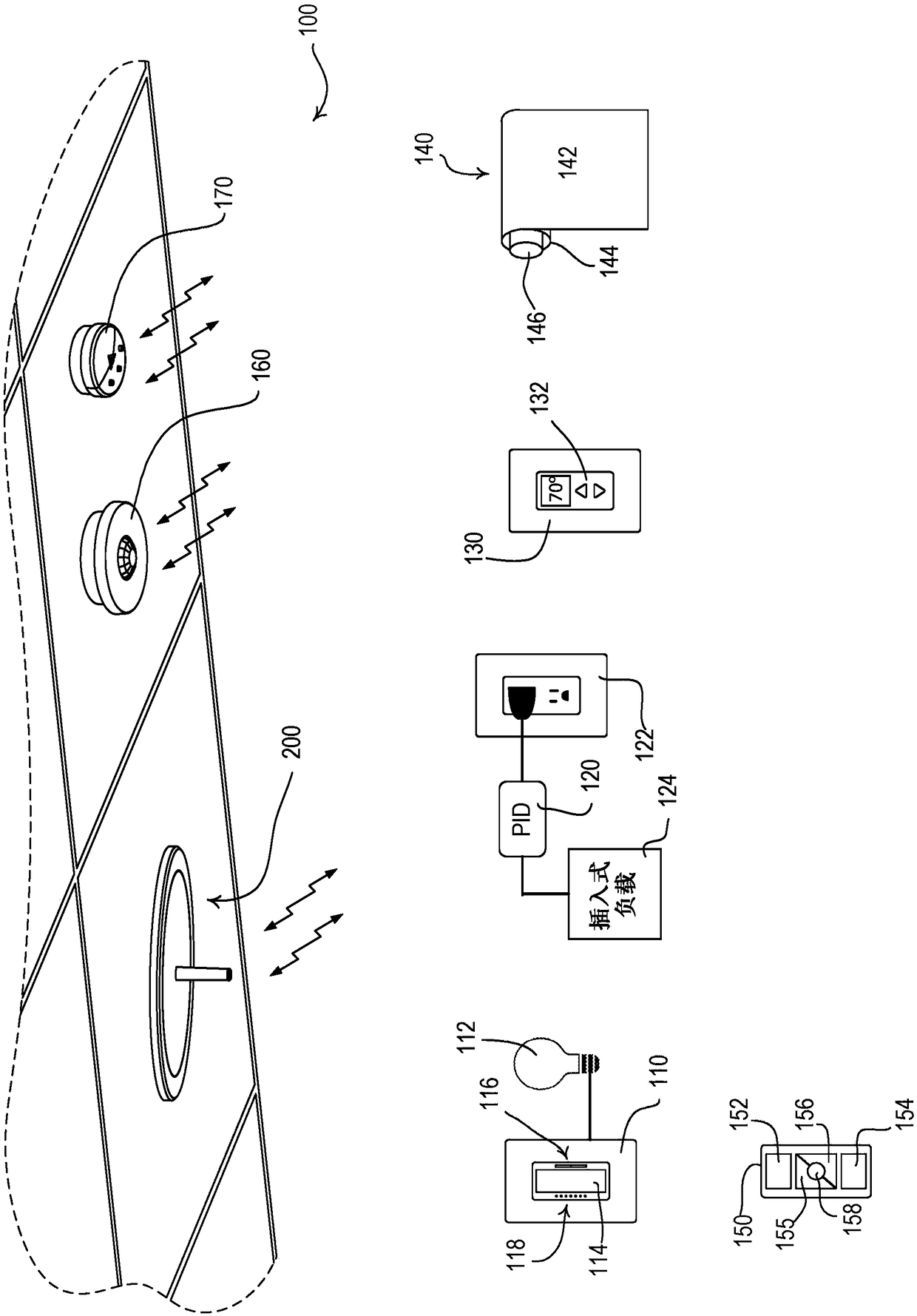
[0019] figure 1 An example load control system 100 is shown. Load control system 100 may include, for example, dimmer switch 110 , plug-in load control device (PID) 120 , temperature control device 130 , powered window treatments 140 , remote control 150 , occupancy sensor 160 , and daylight sensor 170 . Dimmer switch 110 may be coupled in series electrical connection between an alternating current (AC) power source (not shown) and lighting load 112 for controlling the amount of power delivered to the lighting load. The dimmer switch 110 may be adapted to be wall mounted in a standard electrical wall box, or alternatively implemented as a desktop load control device. The dimmer switch 110 may include a dial actuator 114 and / or an intensity adjustment actuator 116 . Actuation of the dial actuator 114 toggles (ie, turns off and on) the lighting load 112, while up and down actuation of the intensity adjustment actuator 116 toggles between minimum intensity (eg, approximately 1%...


PUM


Abstract

A wireless communication device for use in a load control system for controlling one or more electrical loads may comprise a counterpoise, a first and second antennas, a RF communication circuit and acontrol circuit. The two antennas may be oriented differently and spaced apart from each other. For example, the first antenna may extend perpendicularly from the counterpoise while the second antenna extends in a plane substantially parallel to the counterpoise. The first antenna may extend from the counterpoise at a point substantially central to the counterpoise while the second antenna may extend along a perimeter of the counterpoise. The RF communication circuit may transmit wireless signals via the first and second antennas. The control circuit may cause the RF communication circuit totransmit a first wireless signal in a first time slot and a second wireless signal in a second time slot.

Description

[0001] Cross References to Related Applications [0002] This application claims the benefit of Provisional US Patent Application Serial No. 62 / 248,762, filed October 30, 2015. Background technique [0003] Buildings such as residences, office buildings, warehouses, factories, etc. often use load control systems to control electrical loads. Examples of electrical loads include lights, powered window shades, fans, and other energy consuming devices. A load control system may include one or more load control devices such as wall dimmer switches, temperature controllers, motorized window treatments, etc. The load control devices can operate completely independently of each other and at the same time be subject to system-wide control. For example, the central command unit of the load control system may initiate a whole room clock function to set all electrical loads in one mode during the day and in another mode after hours. Accordingly, it is contemplated that the load control...

Claims


Application Information

Patent Timeline
IPC IPC(8): H01Q9/30H01Q9/38H01Q21/24
CPCH04W72/0446H01Q21/24H01Q1/38H01Q1/007H01Q9/30H01Q1/36H01Q1/48H01Q1/2291H01Q5/30H01Q9/38H01Q9/42H01Q5/392H01Q11/08
Inventor 本杰明·F·博德小罗伯特·博林杰唐纳德·R·莫斯布鲁克瓦尔特·S·扎哈尔丘克
Owner LUTRON TECH CO LLC
Why Eureka
Try Eureka