Tubular heating device

A technology of heating device and heating jacket, applied in the field of fire extinguishing system, can solve the problems of prolonging time, damage to inner lining, increasing energy consumption of fire extinguishing agent, etc., and achieves the effect of large heating jacket area

Pending Publication Date: 2018-07-31
FOGTEC BRANDSCHUTZ GMBH & CO KG
View PDF4 Cites 2 Cited by
  • Summary
  • Abstract
  • Description
  • Claims
  • Application Information

AI Technical Summary

Problems solved by technology

On the one hand, this increases the energy consumption for heating the extinguishing agent, and on the other hand, it prolongs the time until the extin

Method used


Image

  • Tubular heating device
  • Tubular heating device
  • Tubular heating device

Examples


Embodiment Construction

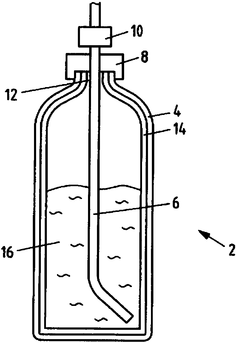
[0063] figure 1 A fire extinguishing system 2 with an extinguishing agent container 4 is shown. Arranged in the extinguishing agent container 4 is a riser 6 , which leads into a valve 10 via an adapter 8 . The adapter piece 8 is seated in the region of the outlet opening 12 of the extinguishing agent container 4 and is preferably screwed tight there.

[0064] In the variant shown, the extinguishing agent container 4 is a steel cylinder whose inner surface has a lining 14 made of plastic in order to protect the material of the extinguishing agent container 4 against corrosion. Extinguishing fluid 16 , here in the form of water, is stored in the extinguishing agent container 4 in a compressed state. The extinguishing agent container 4 is preferably in standby mode with a static pressure of more than 5 bar, preferably more than 20 bar, especially more than 100 bar. By opening the valve 10 , the extinguishing fluid 16 is discharged from the extinguishing agent container 4 via t...


PUM


Abstract

The invention relates to a fire fighting system (2). The fire fighting system (2) comprises a pressure-resistant extinguishant container (4), at least one opening in an outer wall of the extinguishantcontainer (4) and a tube (6) disposed in the opening. An increased operational readiness is achieved in that a flat heating means at least partially surrounds the lateral surface of the tube.

Description

technical field [0001] The invention relates to a fire extinguishing system with a heating device. Background technique [0002] In the field of mobile fire extinguishing systems which are included as the object of the present invention, there is always the risk of freezing of the extinguishing agent when using aqueous extinguishing agents. When water is used as the fire extinguishing agent in the present invention, especially in the high-pressure water mist system of the present invention, the fire extinguishing agent may freeze when the temperature is very low, especially below 0°C. This leads to two problems. On the one hand, water expands when it freezes, so that there is a risk of bursting of the extinguishing agent container, of the valve arranged at the outlet of the extinguishing agent container or of other devices in the extinguishing system. On the other hand, when the extinguishing agent freezes, it is no longer possible to extinguish the fire. Instead, it is f...

Claims


Application Information

Patent Timeline
IPC IPC(8): A62C3/07A62C35/02
CPCA62C3/07A62C35/023A62C35/58A62C13/76
Inventor 罗格·迪克斯迈尔乌尔里希·希尔特曼
Owner FOGTEC BRANDSCHUTZ GMBH & CO KG
Why Eureka
Try Eureka