
Motor drive device

A driving device and motor technology, which is applied in motor control, motor generator control, AC motor control, etc., and can solve problems such as abnormality of the power input part 4 and inability to detect equipment 5 faults, etc.

Active Publication Date: 2018-07-31
FANUC LTD
View PDF11 Cites 0 Cited by
  • Summary
  • Abstract
  • Description
  • Claims
  • Application Information

AI Technical Summary

Problems solved by technology

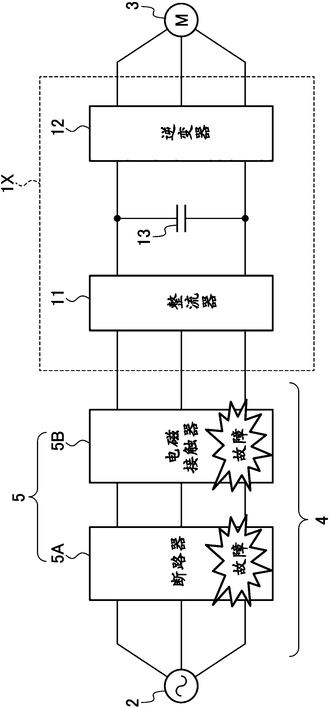
[0008] Thus, in the conventional motor drive device 1X, failure of the device 5 in the power input part 4 provided between the motor drive device 1X and the AC power supply 2 (that is, abnormality of the power input part 4 ) cannot be detected.
In addition, the motor drive devices described in Patent Documents 1 to 3 are not devices for detecting failures of devices installed in the power input unit between the motor drive device and the AC power supply.

Method used


Image

  • Motor drive device
  • Motor drive device

Examples


no. 1 Embodiment approach

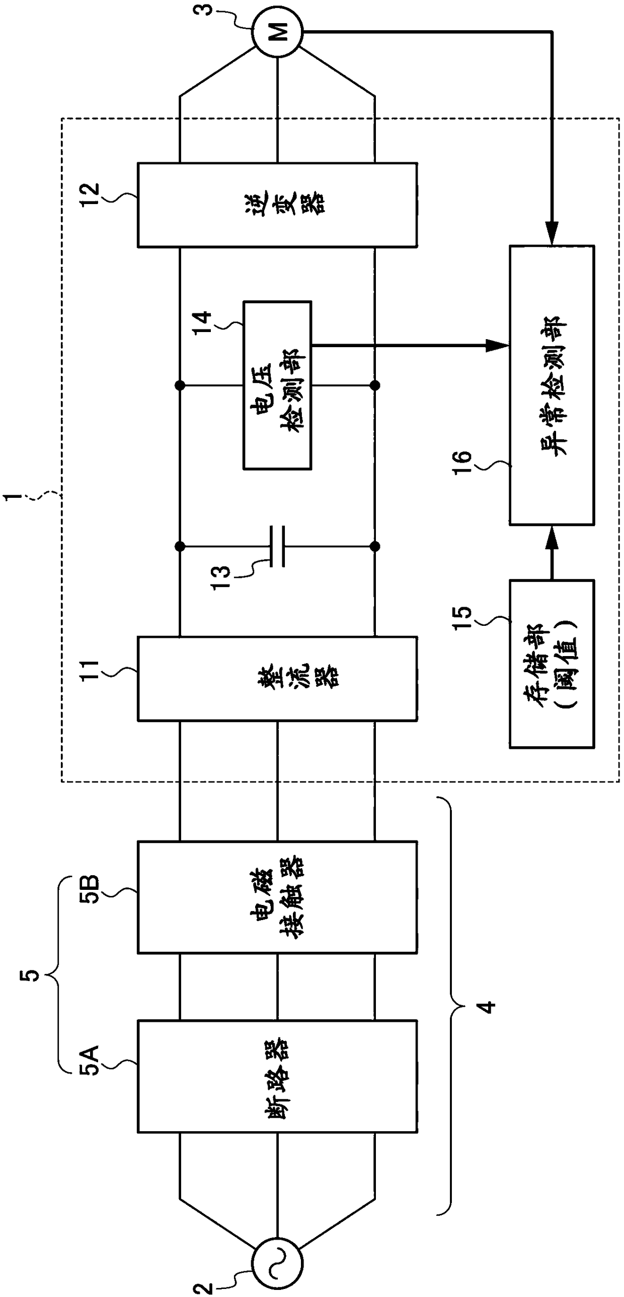
[0036] figure 1 It is a diagram showing the circuit configuration of the motor drive device according to the first embodiment of the present invention. figure 1 The illustrated motor drive device 1 inputs three-phase AC power from a commercial three-phase AC power source 2 and drives a motor 3 . In addition, the AC power supply 2 is not limited to a three-phase AC, and may be a single-phase AC, for example.

[0037] Devices 5 such as a circuit breaker 5A and an electromagnetic contactor 5B are provided in the power input unit 4 between the motor drive device 1 and the AC power supply 2 .

[0038] The motor drive device 1 includes a rectifier 11 , an inverter 12 , a DC link capacitor 13 , a voltage detection unit 14 , a storage unit 15 , and an abnormality detection unit 16 .

[0039] The rectifier 11 converts the AC power from the AC power supply 2 into DC power. The rectifier 11 is constituted by, for example, a diode rectification converter or a PWM converter having a b...

no. 2 Embodiment approach

[0062] In the first embodiment, a failure of the device 5 (abnormality of the power supply input unit 4 ) is detected during acceleration or deceleration of the motor 3 based on the amount of voltage change per unit time of the DC link capacitor 13 . In the second embodiment, a failure of the device 5 (power input unit 4 exception).

[0063] The structure of the motor drive device 1 according to the second embodiment and figure 1 The configuration of the motor drive device 1 of the first embodiment shown is the same. In addition, in the motor drive device 1 according to the second embodiment, the function and operation of the abnormality detection unit 16 and the threshold value stored in the storage unit 15 are different from the motor drive device 1 of the first embodiment.

[0064] The storage section 15 stores in advance a threshold value for detecting a voltage change of the DC link capacitor 13 for a predetermined time due to a failure of the device 5 (ie, an abnormal...


PUM


Abstract

A motor drive device can detect abnormality of a power supply unit. The motor drive device has an abnormality detection function for a power supply input part (4) between the device (1) and a power supply (2), and includes: a rectifier (11) that is inputted AC power from the power supply (2) via the power supply input part (4), and converts the AC power into DC power; a reverse converter (12) thatconverts the DC power from the rectifier (11) into AC power; a DC link capacitor (13) provided to a DC link between the rectifier (11) and the reverse converter (12); a voltage detection part (14) that detects voltage of the DC link capacitor (13); and an abnormality detection part (16) that obtains a voltage change amount for a predetermined time of the DC link capacitor (13) based on voltage values detected by the voltage detection part (14), and performs abnormality detection on the power supply input part (4) based on the voltage change amount thus obtained.

Description

technical field [0001] The present invention relates to a motor drive device having an abnormality detection function of a power input unit. Background technique [0002] There are known motor drive devices that drive motors in machine tools, industrial machines, forging machines, injection molding machines, or various types of robots. figure 2 is a diagram showing an example of such a motor drive device. figure 2 The illustrated motor drive device 1X includes a rectifier 11 that converts three-phase AC power from an AC power source 2 into DC power, an inverter 12 that converts the DC power from the rectifier 11 into three-phase AC power, and converts the three-phase AC power to DC power. Electric power is supplied to the motor 3 . A DC link capacitor 13 is provided in the DC link between the rectifier 11 and the inverter 12 . [0003] Patent Documents 1 to 3 disclose techniques for detecting an abnormality of the device in such a motor drive device. Patent Document 1 de...

Claims


Application Information

Patent Timeline
IPC IPC(8): H02P29/024
CPCH02P29/0241H02M1/32H02M5/453H02P27/06H02P29/025H02P2201/03H02M5/42
Inventor 吉田友和
Owner FANUC LTD
Learn More