Automobile pillar A display system

A technology for display systems and automobiles, applied in vehicle parts, optical observation devices, transportation and packaging, etc., can solve the problems of blind spots in the driver's field of vision, blocking the driver's field of vision, etc., to eliminate blind spots, improve driving comfort, and driving safety. high sex effect

Pending Publication Date: 2018-07-31
HASCO VISION TECHNOLOGY CO LTD
View PDF0 Cites 12 Cited by
  • Summary
  • Abstract
  • Description
  • Claims
  • Application Information

AI Technical Summary

Problems solved by technology

[0002] At present, the main function of the A-pillar of the car is to provide a certain degree of rigidity and improve the safety of the car. The A-pillar is located at the left and right ends of the front of the car and is used to connect the roof and the front cabin. It is this special position above the mirror, whether the car is static or dynamic, it will block part of the driver's vision, resulting in a certain blind spot for the driver's vision.

Method used


Image

  • Automobile pillar A display system
  • Automobile pillar A display system
  • Automobile pillar A display system

Examples


Embodiment 1

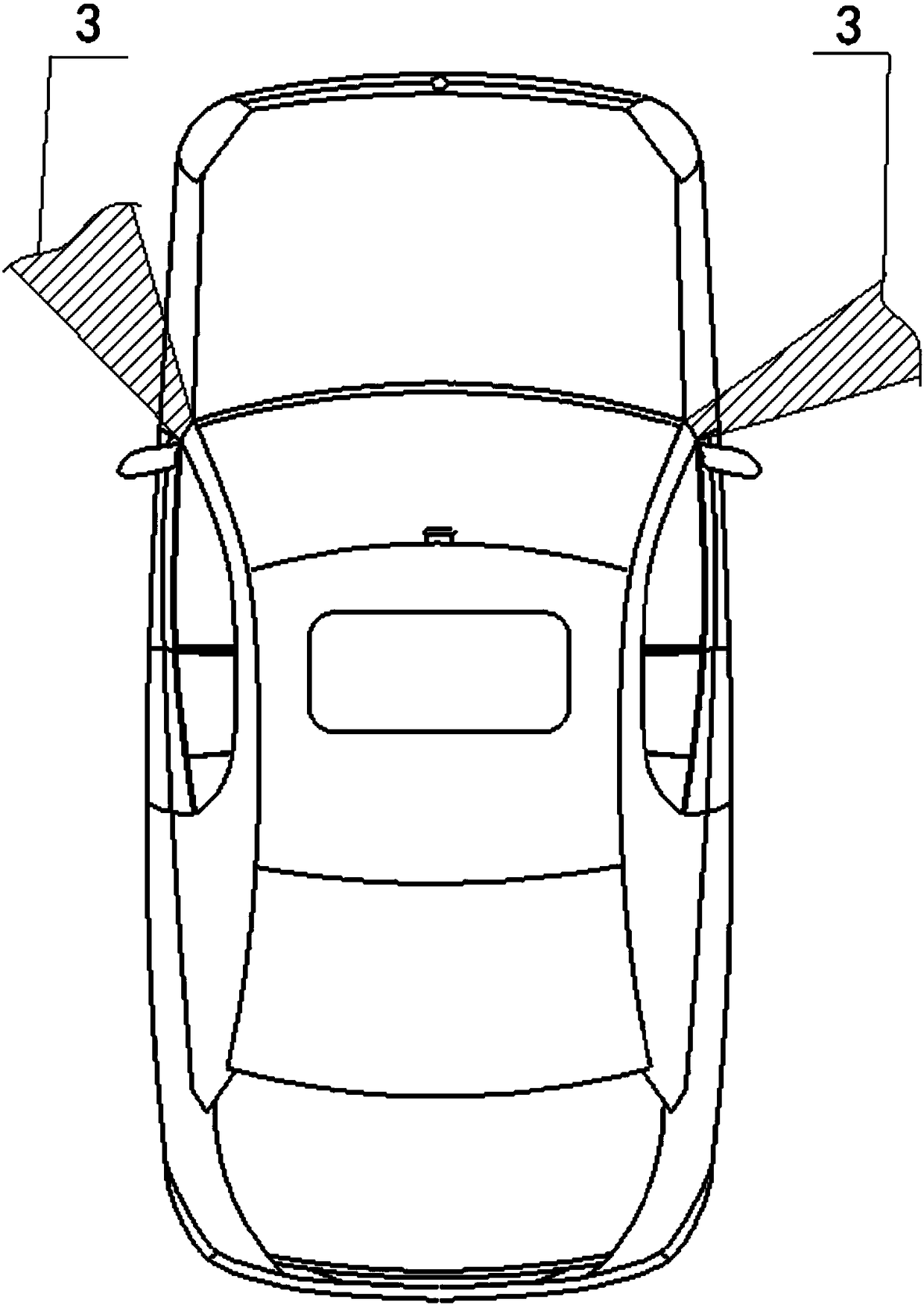
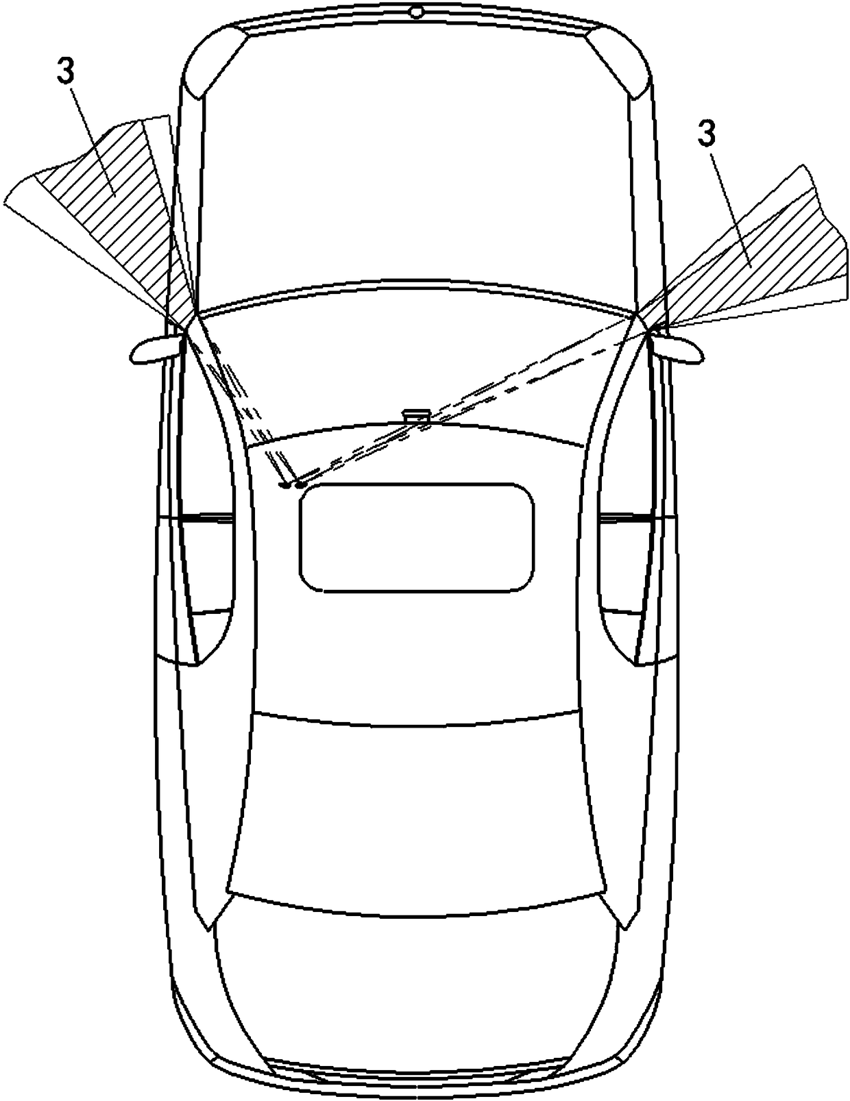
[0055] The automobile A-pillar display system provided in this embodiment is used to eliminate the blind area of ​​the automobile's A-pillar and is placed inside the automobile. like figure 1 As shown, the A-pillars on the left and right sides of the car will create certain blind spots on the left and right sides of the driver respectively, forming the range 3 of the blind spots on the A-pillars, as shown in figure 2 As shown, the range 3 of the A-pillar blind zone is the intersection of the respective blind spots of the driver's left and right eyes.

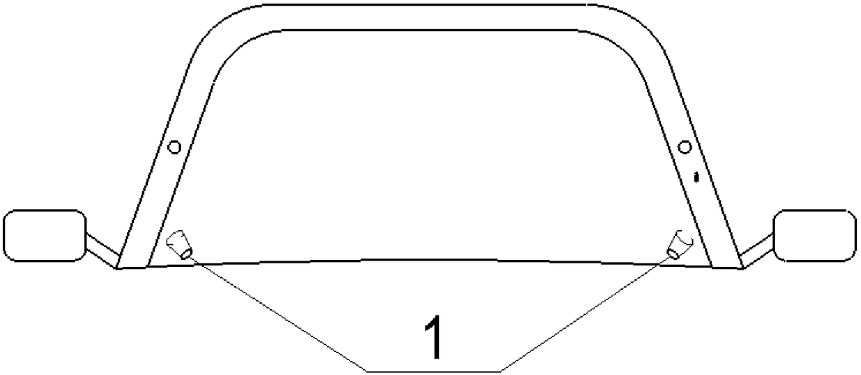
[0056] Specifically, the automobile A-pillar display system includes a blind spot camera 1, a display screen 2, an image processing and display output unit, and a control unit. In this harsh environment such as rain and fog, the effect of the wiper can be used to improve the impact of the environment on the camera. The blind spot camera 1 is connected to the image processing and display output unit by wire, and is connected t...


PUM


Abstract

The invention provides an automobile pillar A display system which comprises a blind area camera, a display screen, an image processing and display output unit, and a control unit, wherein the blind area camera is arranged in a position close to a front windshield inside an automobile and is connected with the image processing and display output unit; the image processing and display output unit is arranged close to the console inside the automobile and is connected with the display screen; the control unit is arranged close to the console inside the automobile and is connected with the blindarea camera; the display screen is arranged on the inner surface inside an automobile pillar A; the area of the display screen is not greater than that of the inner surface of the pillar A; the imageprocessing and display output unit is used for outputting images acquired by using the blind area camera to the display screen. The automobile pillar A display system can be adaptive to different running states of the automobile, different adaptive images can be displayed on the pillar A, and thus relatively high driving security can be achieved; the units are compactly arranged inside the automobile, the response speed and the precision of the system can be improved, and the driving comfort can be improved.

Description

technical field [0001] The invention relates to the technical field of automobiles, in particular to an automobile A-pillar display system. Background technique [0002] At present, the main function of the A-pillar of the car is to provide a certain degree of rigidity and improve the safety of the car. The A-pillar is located at the left and right ends of the front of the car and is used to connect the roof and the front cabin. The top of the mirror is just this special position, whether the car is static or dynamic, it will block part of the driver's vision, resulting in a certain blind spot for the driver's vision. Visibility is more pronounced when cornering, especially left turns. Therefore, it is necessary to eliminate the blind area of ​​the A-pillar through some technologies and improve the safety of driving. Contents of the invention [0003] The purpose of the present invention is to provide an automobile A-pillar display system to at least solve one of the tec...

Claims


Application Information

Patent Timeline
IPC IPC(8): B60R1/00
CPCB60R1/00B60R2300/8026B60R2300/8073
Inventor 仇智平祝贺
Owner HASCO VISION TECHNOLOGY CO LTD
Why Eureka
Try Eureka