
Protection device for several flying objects in blasting

A protective device and flying object technology, applied in blasting and other directions, can solve problems such as low construction efficiency, laborious handling, and heavy workload, and achieve the effects of preventing dust from escaping, ensuring safety, and avoiding pollution

Pending Publication Date: 2018-07-27
WUHAN BLASTING ENG
View PDF5 Cites 1 Cited by
  • Summary
  • Abstract
  • Description
  • Claims
  • Application Information

AI Technical Summary

Problems solved by technology

[0004] However, the above-mentioned structure has the following disadvantages: first, the bamboo springboard is relatively heavy and laborious to carry; secondly, the air permeability of the quilt is poor, which is not conducive to the release of the blast shock wave and affects the safety of the blasting; finally, the protective method of binding the bamboo springboard and wrapping the quilt Heavy workload and low construction efficiency

Method used


Image

  • Protection device for several flying objects in blasting
  • Protection device for several flying objects in blasting

Examples


Embodiment 1

[0025] Such as figure 1 As shown, the present embodiment provides a protection device for blasting individual flying objects, which is installed on a rectangular parallelepiped column and includes a first frame 1 , a second frame 2 , a first protective net 3 and a second protective net 4 .

[0026] Four first frames 1 are arranged on the four sides of the column, and the first protective net 3 is wound on the outside of the first frame 1 in one or more layers, so that the first protective net 3 is close to the column. The second protective net 4 is arranged in the second frame 2, the number of the second frame 2 is the same as that of the first frame 1, the second frame 2 is attached to the first frame 1, and the second frame 2 is connected to the first frame by a fastener. The frame 1 is fixedly connected, and the fastener passes through the mesh of the first protective net 3 . Adjacent second frames 2 are connected by connecting pieces 5 , and there is a gap between the fir...

Embodiment 2

[0035] This embodiment provides a blasting individual flying object protection device, which is installed on a rectangular parallelepiped column. Its structure is substantially the same as that of Embodiment 1, from the inside to the outside are the first frame 1, the first protective net 3, the water bag 6 and the second frame 2 with the second protective net 4 installed. The difference is that due to the different shapes of the columns, the shapes of the first frame 1 attached to it and the second frame 2 attached to the first frame 1 also change accordingly.

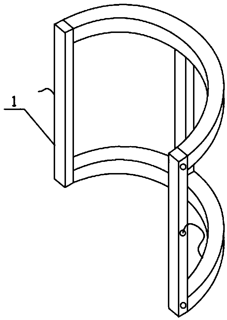
[0036] Such as figure 2 As shown, both the first frame 1 and the second frame 2 are composed of two parallel semicircular rods and a support rod connecting the two semicircular rods, and both the first frame 1 and the second frame 2 are two. Adjacent first frames 1 are connected through connecting pieces 5 , and adjacent second frames 2 are connected through connecting pieces 5 .


PUM


Abstract

The invention discloses a protection device for several flying objects in blasting. The protection device comprises a plurality of first frames, second frames, first protection nets and second protection nets. The multiple first frames are arranged on the side face of a vertical column, and the first protection nets are wound around the outer sides of the first frames in one or more layers. The second protection nets are arranged in the second frames. The second frames and the first frames are the same in number. The second frames are fixedly connected with the first frames through fasteners,and the fasteners penetrate through meshes of the first protection nets. The adjacent second frames are connected through connecting pieces. Gaps are reserved between the first protection nets and thesecond protection nets. According to the protection device, the gaps are reserved between the first protection nets and the second protection nets, so that the mechanical property of the first protection nets is given to full play, secondary protection is achieved, and safety is guaranteed; the parts, on the four first frames, of the first protection nets are all in a tensioned state due to fixing of the fasteners, and the four side faces are not affected with one another; and even if a certain side face is partially damaged, the mechanical property of the rest part of the side face is not affected.

Description

technical field [0001] The invention relates to the technical field of demolition blasting, in particular to a protection device for individual flying objects from blasting. Background technique [0002] In urban reconstruction and expansion projects, a large number of houses built in the 1960s and 1970s are facing demolition. Compared with manual and mechanical demolition methods, blasting demolition technology is recognized as the safest, most efficient and economical method. In the field of blasting demolition, columns and beams of concrete structures are the most common drilling and blasting objects. The basic principle of using the drilling and blasting method to demolish a concrete structure building is to use the energy released instantly by the explosive explosion to destroy key supporting components such as columns and beams of the building, so as to achieve the purpose of causing the building to lose stability and collapse under the action of gravity. The basic pr...

Claims


Application Information

Patent Timeline
Patent Type & Authority Applications(China)
IPC IPC(8): F42D5/045
CPCF42D5/045
Inventor 贾永胜刘昌邦姚颖康韩传伟黄小武王洪刚朱梦成严涛
Owner WUHAN BLASTING ENG
Learn More