chain lock

A chain lock and chain technology, applied in the field of chain locks, to achieve the best anti-theft effect and the effect of not being easily damaged

Inactive Publication Date: 2019-07-05
RERLLY IND
View PDF5 Cites 1 Cited by
  • Summary
  • Abstract
  • Description
  • Claims
  • Application Information

AI Technical Summary

Problems solved by technology

[0003] The main purpose of the present invention is to provide a chain lock, which can effectively solve the shortcomings of existing chain locks in use.

Method used


Image

  • chain lock
  • chain lock
  • chain lock

Examples


Embodiment Construction

[0022] Regarding the technical means adopted by the present invention in order to achieve the above-mentioned use purposes and effects, a preferred and feasible embodiment is presented and shown in the drawings, and the details are as follows:

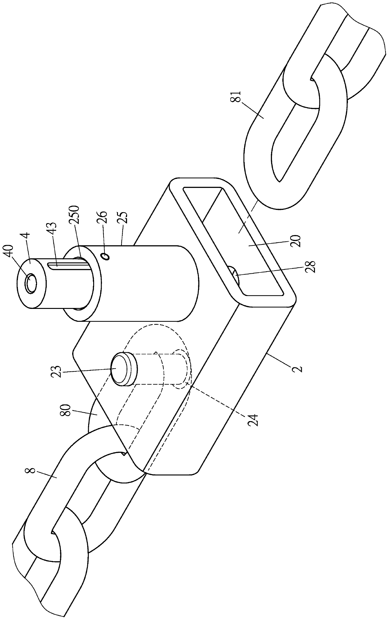
[0023] For examples of the present invention, please refer to figure 2 , image 3 , Figure 4 , Figure 5 As shown, a lock body 2 is mainly provided. The lock body 2 is provided with a chain slot 20. The top surface of the lock body 2 is provided with a first perforation 21 connected to the chain slot 20. The bottom surface of the lock body 2 corresponds to A second through hole 22 is provided at the position of the first through hole 21. A fixing bolt 23 penetrates through the first through hole 21 and the chain slot 20 and penetrates into the second through hole 22. One end of the fixed bolt 23 A ring groove 230 is provided on the part, a positioning sleeve 24 is inserted into the second through hole 22 of the lock body 2 and sleeved on...


PUM


Abstract

The invention provides a chain lock. The chain lock mainly comprises a lock body, a compression spring, a lock cylinder seat, a lock cylinder, a connecting seat, an inserting rod and a chain, whereina chain inserting groove is formed in the lock body; the compression spring is arranged in an accommodating chamber of a convex seat of the lock body; the lock cylinder seat is also located in the accommodating chamber of the convex seat of the lock body; the lock cylinder is arranged in an accommodating groove of the lock cylinder seat; the connecting seat is arranged below the lock cylinder seatand arranged in the accommodating chamber of the lock body and abuts against the compression spring; the upper end of the inserting rod penetrates through a penetrating hole of the connecting seat and is inserted in an inserting groove of the lock cylinder, and the bottom end of the inserting rod penetrates through a through hole of the lock body; one end of the chain is fixedly arranged in one end of the chain inserting groove of the lock body by a fixing bolt, and the other end of the chain is buckled in the other end of the chain inserting groove of the lock body through the inserting rod.Therefore, articles can be locked conveniently, and the optimal anti-theft effect can be realized.

Description

Technical field [0001] The invention relates to a chain lock, in particular to an article that can be easily locked and can achieve the best anti-theft effect. Background technique [0002] A general chain lock is mainly used to lock objects on a fixed object, for example, to lock a bicycle on a pillar, and the structure of the general chain lock 1, such as figure 1 As shown, the two ends of a chain 10 are connected with a lock 11 that can be locked together. The lock 11 is a matching lock or a padlock, which mainly prevents the locked items from being moved to prevent the items from being locked. theft. However, in the existing chain lock 1, the lock 11 and the chain 10 are separated, the lock 11 is easy to lose, and the lock structure of the lock 11 is extremely simple. The thief can easily unlock or damage the lock 11 with a tool. The anti-theft effect is not ideal. Summary of the invention [0003] The main purpose of the present invention is to provide a chain lock that can...

Claims


Application Information

Patent Timeline
Patent Type & Authority Patents(China)
IPC IPC(8): E05B67/00E05B15/04E05B15/10E05B15/14
CPCE05B15/04E05B15/10E05B15/14E05B67/003E05B2015/0424
Inventor 林郁宾
Owner RERLLY IND
Why Eureka
Try Eureka