
Automatic feeding mechanism of CNC high-speed machining center

A processing center and automatic feeding technology, which is applied in the direction of metal processing machinery parts, metal processing, metal processing equipment, etc., can solve the problems of not being able to drill on multiple sides, low drilling efficiency, inaccurate positioning, etc., and achieve good fixing effect , Easy to process drilling, fast feeding effect

Inactive Publication Date: 2018-07-27
江苏瑞苏科技有限公司
View PDF8 Cites 2 Cited by
  • Summary
  • Abstract
  • Description
  • Claims
  • Application Information

AI Technical Summary

Problems solved by technology

[0003] The present invention provides a CNC high-speed machining center automatic feeding mechanism, which solves the problems of difficult clamping, inaccurate positioning and low drilling efficiency of the existing drilling machine encountered in the above background technology, and can only be drilled on one side. Holes, the problem of not being able to drill holes on multiple sides

Method used


Image

  • Automatic feeding mechanism of CNC high-speed machining center
  • Automatic feeding mechanism of CNC high-speed machining center

Examples


Embodiment

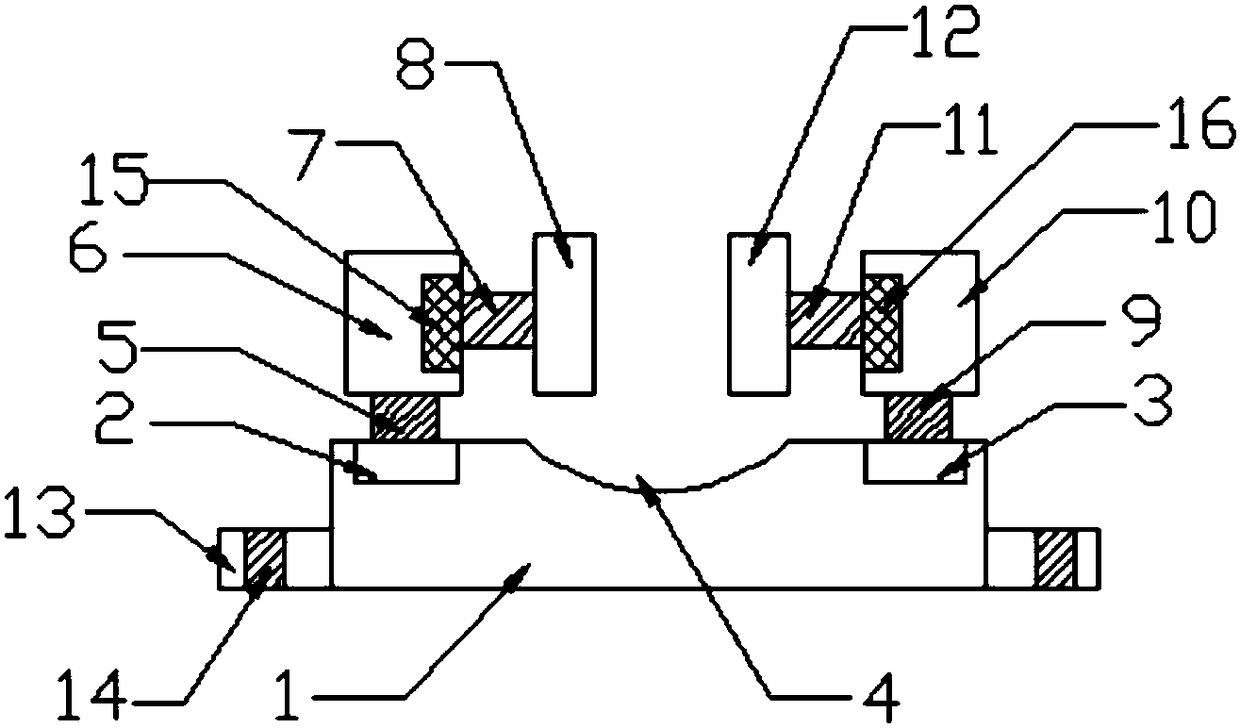
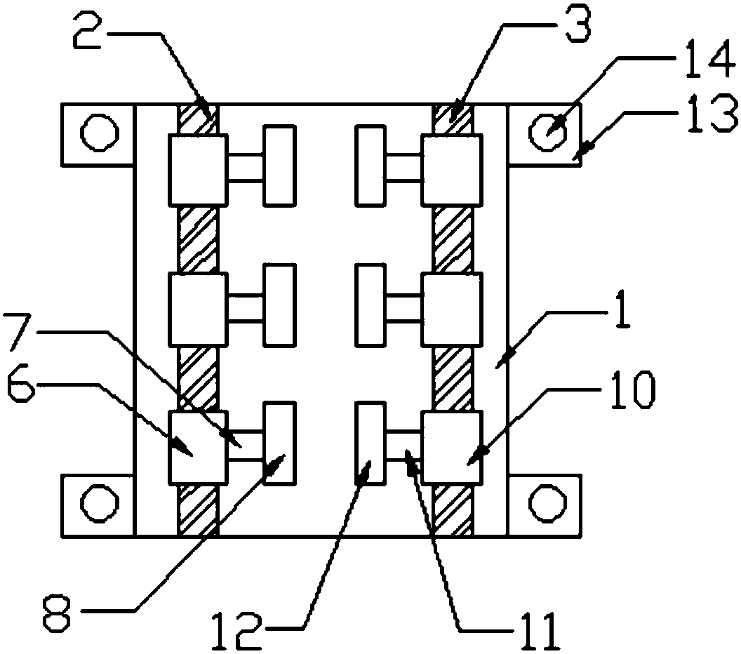
[0017] Example: such as Figure 1-2 As shown, a CNC high-speed machining center automatic feeding mechanism of the present invention includes a base 1, the top of the base 1 is provided with a first chute 2, a second chute 3, and a groove 4, and the groove 4 is arranged on the first chute Between the groove 2 and the second chute 3, the first chute 2 is provided with a first electric slider 5, the top of the first electric slider 5 is provided with a first fixed block 6, and one end of the first fixed block 6 is provided with There is a first electric rotary table 15, one side of the first electric rotary table 15 is provided with a first electric telescopic rod 7, one side of the first electric telescopic rod 7 is provided with a first splint 8, and the second chute 3 is provided with There is a second electric slider 9, the top of the second electric slider 9 is provided with a second fixed block 10, one end of the second fixed block 10 is provided with a second electric rot...


PUM


Abstract

The invention discloses an automatic feeding mechanism of a CNC high-speed machining center. The automatic feeding mechanism comprises a base, a first sliding groove, a second sliding groove and a groove are formed in the top end of the base, and a first electric sliding block is arranged on the first sliding groove; first fixing blocks are arranged at the top end of the first electric sliding block, and first electric rotary tables are arranged at one ends of the first fixing blocks; first electric stretchable rods are arranged on one sides of the first electric rotary tables, one sides of the first electric stretchable rods are provided with first clamping plates, and a second electric sliding block is arranged on the second sliding groove; second fixing blocks are arranged at the top end of the second electric sliding block, and second electric rotary tables are arranged at one ends of the second fixing blocks; and second electric stretchable rods are arranged on one sides of the second electric rotary tables, and second clamping plates are arranged on one sides of the second electric stretchable rods. The steel material needing to be machined is continuously transferred to thelower portion of a numerical control machine tool machining device to be machined and drilled, and the automatic feeding mechanism is good in the fixing effect; the material can be rapidly fed, and the steel needing to be drilled can be driven to rotate; and multi-surface hole drilling can be carried out, so that the working efficiency is improved.

Description

technical field [0001] The invention relates to the technical field of machinery, in particular to an automatic feeding mechanism of a CNC high-speed machining center. Background technique [0002] When making profiles such as C-shaped steel and U-shaped steel in building materials, the existing production is to roll the plate into the above-mentioned shaped profiles through a rolling mill. When this profile is in use, it is necessary to drill holes on its surface or side edges, but the existing drilling machines have the disadvantages of difficult clamping, inaccurate positioning and low drilling efficiency, and can only be drilled on one side, not multiple sides. Drilling, therefore providing a feeding mechanism that is convenient for clamping and fixing, can feed quickly to improve efficiency, and can perform multi-sided drilling solves the problems existing in the drilling machine. Contents of the invention [0003] The present invention provides a CNC high-speed mach...

Claims


Application Information

Patent Timeline
IPC IPC(8): B23Q3/06B23Q7/00
CPCB23Q3/06B23Q7/00
Inventor 张先君
Owner 江苏瑞苏科技有限公司
Learn More