Infrared thermal imaging camera non-uniform correction baffle test method for temperature-variable radiation materials

An infrared thermal imager and non-uniform correction technology, which is applied in image communication, television, electrical components, etc., can solve the problem of poor imaging effect of non-uniform correction, achieve the elimination of non-uniformity, improve imaging quality, and eliminate image non-uniformity. The effect of uniformity

Active Publication Date: 2020-02-14
LUOYANG INST OF ELECTRO OPTICAL EQUIP OF AVIC
View PDF5 Cites 0 Cited by
  • Summary
  • Abstract
  • Description
  • Claims
  • Application Information

AI Technical Summary

Problems solved by technology

In order to solve the problem of poor non-uniform correction imaging effect after working for a long time, it is of great significance to study the non-uniform correction method of the new cooling infrared detector

Method used


Image

  • Infrared thermal imaging camera non-uniform correction baffle test method for temperature-variable radiation materials

Examples


Embodiment Construction

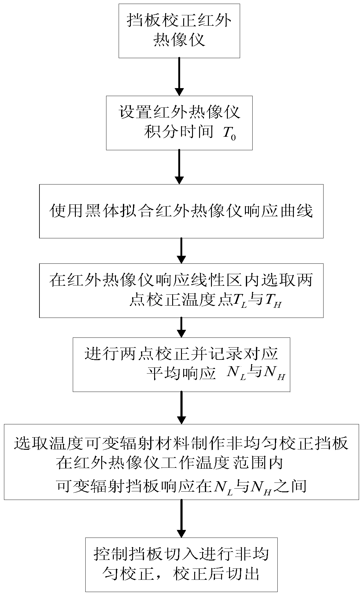
[0029] Now in conjunction with embodiment, accompanying drawing, the present invention will be further described:

[0030] The present invention consists of an infrared imaging component (including an infrared detector), a measured non-uniform correction baffle, an optical system, etc., to form an infrared thermal imager. The infrared thermal imager uses a medium-wave 640×512 area array F4 detector, and the specific implementation steps are as follows:

[0031] Step 1: According to the F number of the detector, determine the actual integration time of the infrared camera to be 12ms;

[0032] Step 2: Under the condition that the integration time is 12ms, the infrared thermal imager collects temperature points against the blackbody. It is required that the blackbody target surface completely covers the infrared thermal imager field of view, and the distance between the infrared thermal imager and the blackbody target surface is not greater than 200mm. This distance was kept cons...


PUM


Abstract

The invention relates to a non-uniformity correction baffle test method for an infrared thermal imager based on a temperature variable radiation material. The temperature variable radiation material is introduced into the field of infrared imaging, after the working environment temperature of the infrared thermal imager changes, when adopting a temperature variable-based infrared radiation material to ensure the non-uniformity correction, a correction baffle response is in a two-point correction linear region; in the case of not increasing the extra overhead of software and hardware systems and not changing the system integration time, the non-uniformity caused by the environment temperature change can be eliminated; and after the picture of the infrared thermal imager has a non-uniformityphenomenon due to the change of the working environment temperature, in the case of not changing the system integration time and not increasing the extra overhead of the software and hardware systems, the picture non-uniformity caused by the environment temperature change can be eliminated, and the imaging quality of the infrared thermal imager can be improved.

Description

technical field [0001] The invention belongs to the application field of infrared thermal imaging cameras, and relates to a method for testing a non-uniform correction baffle of an infrared thermal imaging camera with a baffle to correct an infrared thermal imaging camera, in particular to a non-uniform correction baffle of an infrared thermal imaging camera with a temperature-variable radiation material board test method. Background technique [0002] The infrared detector is the core device of the infrared thermal imager. Due to the manufacturing process and other reasons, the infrared detector has serious non-uniformity in imaging, so the infrared thermal imager needs to be corrected for non-uniformity after it is powered on for the first time or after working for a long time. , to improve image quality. At present, thermal imaging cameras usually use a method of combining two-point and single-point non-uniformity correction. After the infrared thermal imager is assemble...

Claims


Application Information

Patent Timeline
Patent Type & Authority Patents(China)
IPC IPC(8): H04N17/00
CPCH04N17/002
Inventor 张广伟徐华楠孙小亮王凯朱寅非汪江华
Owner LUOYANG INST OF ELECTRO OPTICAL EQUIP OF AVIC
Why Eureka
Try Eureka