


Quick Research
Generate reliable direction feasibility study reports for your R&D in just a few steps.

Technical Q&A
Discover and master advanced knowledge NOW. Basics, ideas, possibilities, all at once.

Find Solutions
As an expert in R&D theories, this can generate solutions to your technical problems instantly.

Evaluate Feasibility
Analyze your overall solution with one click, know your potential R&D risks in advance.

Monitor Landscape
Get weekly tech updates, stay abreast of the latest tech innovations and key insights.
Photovoltaic glass with reflective portions and photovoltaic module
A photovoltaic glass and photovoltaic module technology, applied in photovoltaic power generation, electrical components, semiconductor devices, etc., can solve the problems of reducing incident light, small amount of light, and large light attenuation, and achieve the goal of improving power generation efficiency, shortening distance, and increasing height Effect
- Summary
- Abstract
- Description
- Claims
- Application Information
AI Technical Summary
Problems solved by technology
Method used
Image

Examples
Embodiment 1
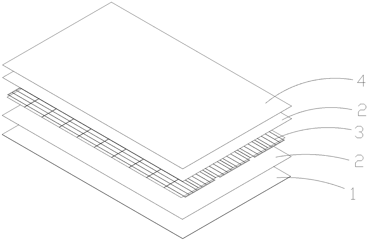
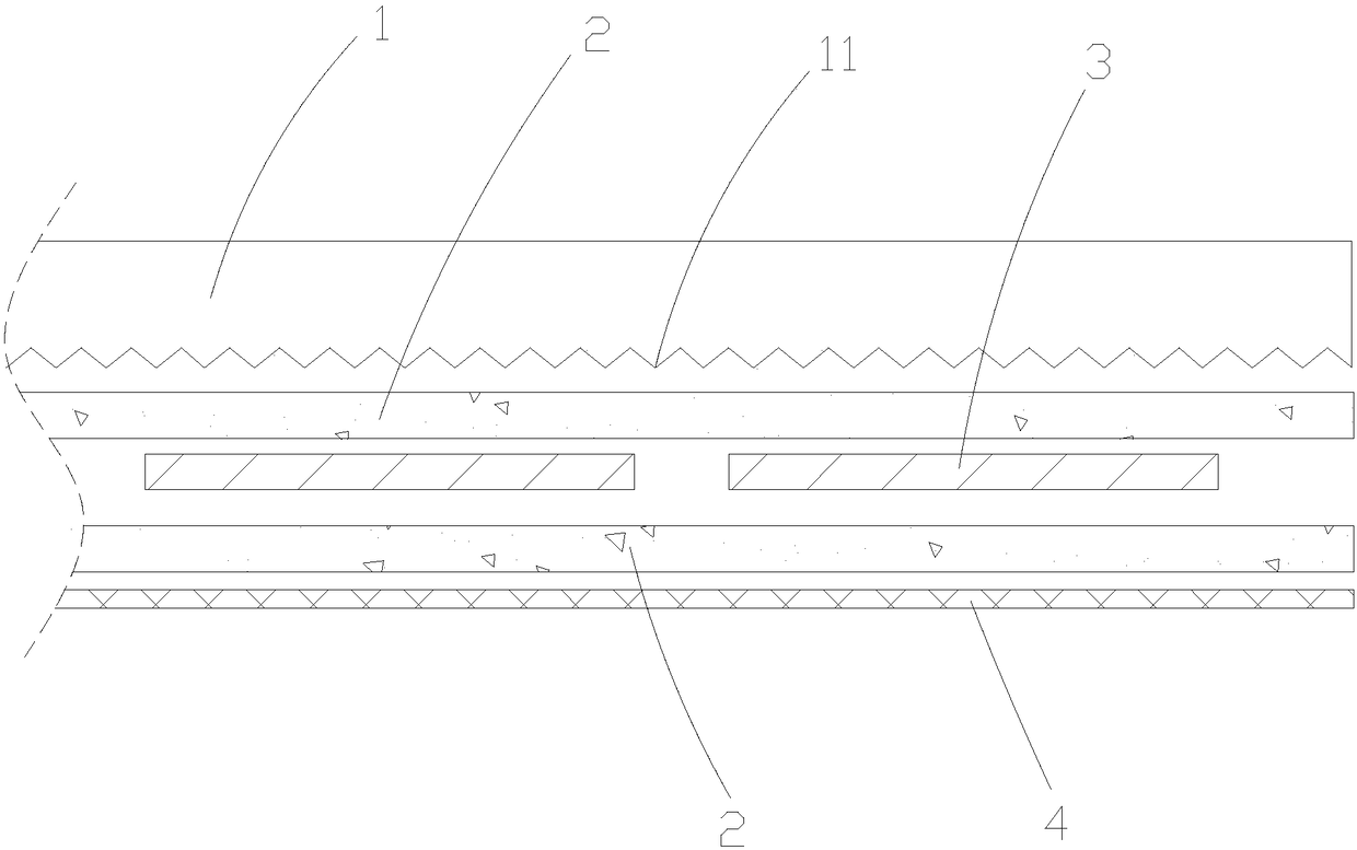
[0050] refer to Figure 5, a photovoltaic module of this embodiment, including a front plate, a front encapsulation layer, a battery layer, a rear encapsulation layer, and a rear plate 4 arranged sequentially from top to bottom, at least one of the front plate and the rear plate 4 is provided with a reflective Section 5 of the photovoltaic glass. In this embodiment, the front panel is selected as the photovoltaic glass 1 provided with the reflective part 5, and the rear panel 4 is conventionally provided. The front encapsulation layer and the rear encapsulation layer are encapsulation film 2 made of conventional materials such as EVA and POE. The battery layer includes several regularly arranged battery sheets 3 .
[0051] In this embodiment, the photovoltaic glass 1 with the reflective part 5 is provided with an embossed structure 11 on the side close to the battery sheet 3, and the embossed structure 11 is in the shape of a zigzag, a pyramid, a triangular strip, a continuo...
Embodiment 2
[0060] refer to Figure 6 , the photovoltaic module of this embodiment is basically the same as that of Embodiment 1, the difference is that: in this embodiment, the reflective part 5 near the edge of the photovoltaic glass 1 is arranged obliquely.
[0061] The width of the reflective part 5 is set according to the actual use situation, as in the present embodiment, the width of the reflective part 5 corresponding to the gap of the cell sheet 3 is the same as the width of the gap of the cell sheet 3, while the reflective part 5 located at the edge of the photovoltaic glass 1 The width of the light reflector 5 can be appropriately expanded according to the inclination angle of the reflective part 5, so as to reflect more incident light to the front of the battery sheet 3.
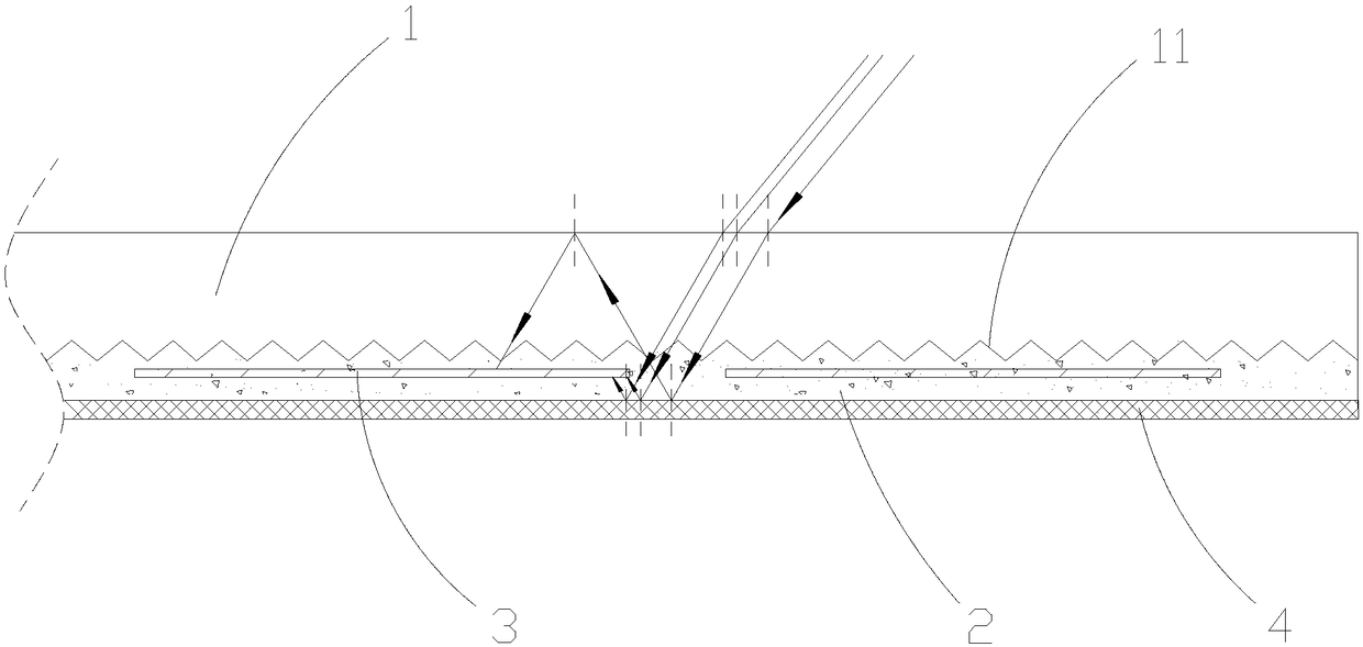
[0062] Figure 6 The middle arrow represents the propagation direction of the light. It can be seen that after the light irradiates the reflective part 5, the incident light is reflected to the upper surfac...
Embodiment 3
[0064] refer to Figure 7-10 , the photovoltaic module of this embodiment is basically the same as that of Embodiment 2, the difference is that: the reflective part 5 corresponding to the gap between the cells 3 in the photovoltaic glass 1 of the photovoltaic module of this embodiment is set in an inverted "V" shape, as Figure 7 and Figure 10 As shown, the reflective part 5 near the peripheral edge of the photovoltaic glass 1 is planar and inclined, as Figure 7 and Figure 9 shown. The width of the reflective portion 5 is set according to the actual usage. The reflective part 5 in this embodiment is arranged vertically and continuously corresponding to the gap between the adjacent battery sheets 3, as Figure 8 and Figure 14 shown.
[0065] Figure 7 The middle arrow represents the propagation direction of the light. It can be seen that after the light irradiates the reflective part 5, the incident light is reflected to the upper surface of the photovoltaic glass 1 ...
PUM
 Abstract
Description
Claims
Application Information
 - R&D Engineer
- R&D Manager
- IP Professional
- Industry Leading Data Capabilities
- Powerful AI technology
- Patent DNA Extraction
Browse by: Latest US Patents, China's latest patents, Technical Efficacy Thesaurus, Application Domain, Technology Topic, Popular Technical Reports.
© 2024 PatSnap. All rights reserved.Legal|Privacy policy|Modern Slavery Act Transparency Statement|Sitemap|About US| Contact US: help@patsnap.com